Sections to 3D Polylines
This command creates 3D polylines from a section (.SCT) file. Besides the section file, a centerline polyline, centerline file or section alignment (.MXS) file must be specified to define the plan view location of the 3D polylines. The elevations for the 3D polylines come from the section file. These 3D polylines can then be used by other Carlson routines to create surface models.
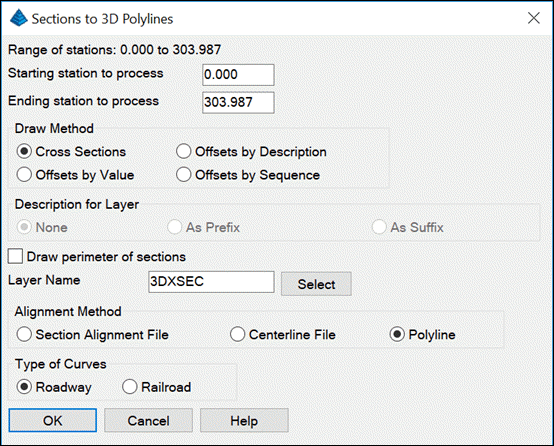
In
the options, dialog set the range of stations to draw and the Layer
Name for the 3D polylines.
The
Draw Methodhas four options:
Description for Layer:This option uses the section point
descriptions in the layer names for the 3D polylines when using the
Offsets By Description method.
Draw perimeter of sections:
This option will connect all the left most offsets and right
most offsets together with a 3D polyline.
Alignment Method:Chooses how to define the horizontal
alignment.
Type of Curves:This option chooses between roadway and
railroad methods for stationing along curves.
Choose Section File to ProcessSelect the .sct file
Cross Section:
The
3D polylines are drawn as cross-sections perpendicular to the
centerline at each station.
Offsets By Description:The 3D polylines are drawn parallel
to the centerline by connecting section points when the same
description. To use this method, the SCT file must have
descriptions on the section points.
For
example, if the section file has descriptions for each section
point then you can draw 3D polylines for EP, SHD, TIE, etc.
Offsets By Value:The 3D polylines are drawn parallel to the
centerline at a specified offset value.
Offsets By Sequence:The 3D polylines are drawn parallel to
the centerline by connecting section points by their sequence in
the section file. For example, a 3D polyline will connect all the
1st section points, another 3D polyline will connect all the 2nd
section points, etc. This method requires the sections to have the
same number of data points for each station.
Prompts
Sections to 3D Polylines dialogChoose your settings
Select centerline polyline:
pick the polyline
Enter the centerline starting station <0.0>:
press Enter
Use reference profile to interpolate between sections
[<Yes>/No]?
N for no.This option will prompt for a profile to use for
interpolating elevations along the 3D polylines between the section
stations. This improves the accuracy when the profile goes through
vertical curves. Without the profile, the 3D polyline elevations
will be straightline interpolated between the sections.
Draw all template ids or specific ids and offsets
[All/<Specific>]?
press Enter for Specific
Enter Offset or Description to draw:
EP
Pulldown Menu Location:
Sections > Section
Utilities
Keyboard Command: scto3dp
Prerequisite:A section (.SCT) file