This command allows you to view a block model in
the 3D viewer window directly from the .blk file. When the command
is executed, you will be prompted to select a .blk file and a grade
parameter file (.gpf file - controls coloring of the blocks). After
selecting these files, the below dialog will appear.
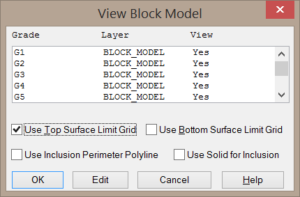

Draw Grade: When enabled, the selected grade category will be drawn in the 3D Viewer.
Layer Name: This field sets the layer name for the blocks.
Color: This button allows you to select a new color for the blocks within the selected grade.
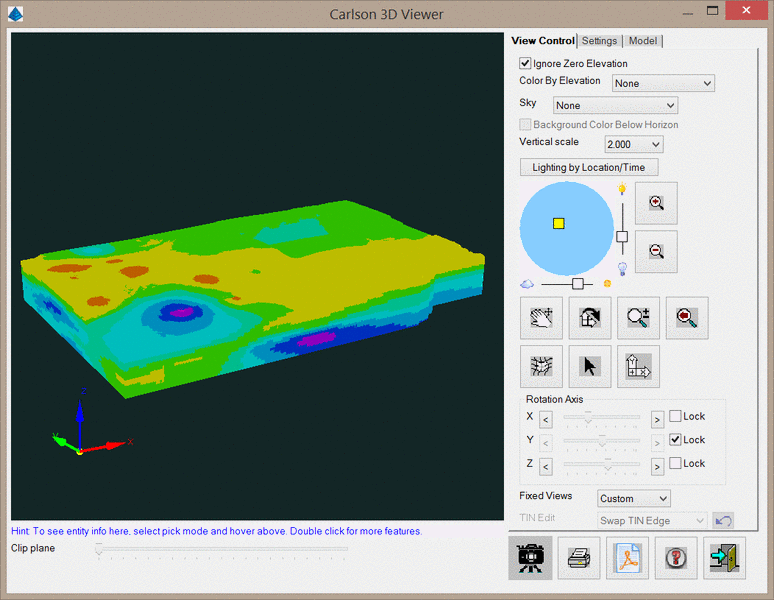
After selecting these settings and clicking OK, the
3D Viewer window will be displayed as shown below. All controls for
this dialog are discussed in the 3D
Viewer Window section of the help manual.
Pulldown Menu Location:
Block Model
Keyboard Command:
blkm_cube
Prerequisite: A BLK model
file and a GPF grade parameter file.