


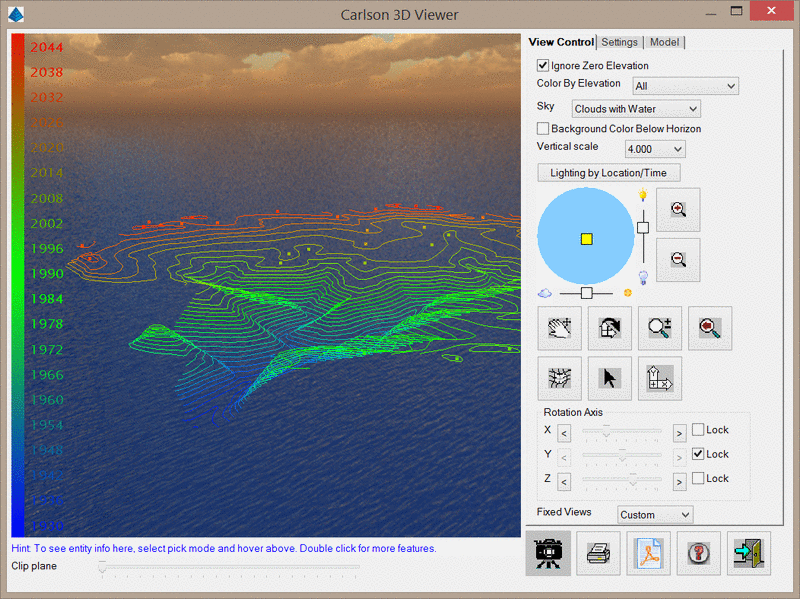
This command loads the selected 3D faces, blocks, polylines,
lines and points into a separate 3D Viewer window. Some of the
features of this viewer include the ability to zoom in and out,
pan, rotate around the X-Y-Z axes, and shade entities with
user-positioned lighting.
The 3D Viewer Window has several mouse and keyboard controls
that can assist with navigating the scene. These are listed
below:
Ignore Zero Elevations: When enabled, the 3D viewer will not display entities at zero elevation.
Color By Elevation: This will color the entities by elevation.
The None option will not modify
the color of entities in the viewer.
The All option will color all entities by
elevation. The elevation color legend will be
displayed on the left of the window and can be adjusted via the
Color By Elevation Scale controls.
The Surface Only option will only
color surface files by elevation. Other entities such as polylines
and 3D faces will not be colored by elevation.
Sky: This
option controls the background image for the 3D viewer. By default,
no background image will be displayed. When a background image is
displayed, you can toggle the Background Color Below Horizon
checkbox to hide the bottom half of the background
image.
Vertical Scale: This option sets the vertical scale factor for the 3D viewer.
Lighting by Location/Time: This button will display the below dialog, which allows you to set the lighting as it would appear at a specific location at a specific time.
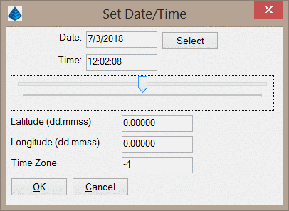
Date/Time: These values set the date and time for the lighting. The Select button will allow you to pick the date from a calendar. The horizontal slider below the time will allow you to set the time of day.
Latitude/Longitude: These values set the location of the viewpoint
Time Zone: This value adjusts for the various time zones. Values should be integers representing GMT adjustments. For example, the Eastern Standard Time (EST) in the USA will use a value of -5.
| Control | Action |
|---|---|
|
|
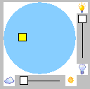
This control represents the position of the sun in plan view. If the yellow square is in the center of the blue circle, the sun is in a zenith. If the yellow square is near the edge of the circle, the sun is near the horizon. To move the yellow square, simply drag it to a new location, or click on the new location. The slider bars on the sides control the intensity and brightness of the display. |
|
|
Switch to Pan mode. Click and drag to pan. |
|
|
Switch to Rotation mode. When the cursor is placed near the outer edge of the view, a "Z" cursor is presented that permits rotation around the Z-axis. When the cursor is placed further into the interior of the view, an "X,Y" cursor is presented that permits the tilt angle of the view to be adjusted. |
|
|
Switch to Dynamic Zoom mode. Click and drag to
zoom in and out. |
|
|
Zoom Previous. |
|
|
Toggle shading of 3D Faces and Surfaces. The shading of these entities is controlled by the Shading Mode control. |
|
|
Switch to Pick mode. In this mode, hovering over an entity will
display data such as the layer, entity type, elevation, and length.
Double-clicking an entity permits additional actions to be
performed on the entity including the ability to change the layer
of the entity and/or setting the entity to an elevation of zero
(0). When hovering over a surface, the coordinates and slope of the
surface at the cursor location will be displayed. |
|
|
Resets the 3D view to plan. |
Rotation Axis: Permits the use of "slider" controls to orient the view in the X, Y and/or Z axis direction(s). Axes may be locked to prevent rotation about that axis.
Fixed Views: Permits the view to be displayed from one of six different directions:
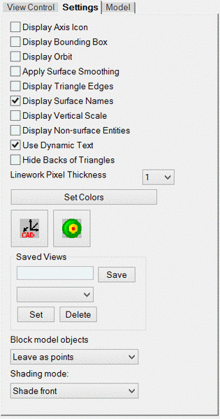
Display Axis Icon: This option toggles the display of the X-Y-Z axes icon in the lower left corner of the window.
Display Bounding Box: This option toggles the display of a 3D box around the limits of the data.
Display Orbit: This option toggles the display of a graphic guide for controlling the view angle and position using the mouse movements similar to the AutoCAD Orbit routine.
Apply Surface Smoothing:
This option shades 3D faces in a way that
appears to remove sharp transitions from one entity to another.
This option affects both surfaces and solids.
Display Triangle Edges: This option toggles the edge lines of triangles that make up surfaces. The triangle edge color can be set with the Set Colors button.
Display Surface Names: This option toggles the display of the file names for the surfaces currently being viewed.
Display Vertical Scale: This options toggles the display of the vertical scale.
Display Non-Surface Entities:
This option toggles the display of entities
that have been tagged as "non-surface" by the
Tag Non-Surface Entities/Points commands.
Use Dynamic Text: This option
automatically resizes and rotates text entities so that they are
always readable. When the option is first enabled, you will need to
restart the viewer for the changes to take effect.
Hide Backs of Triangles: This
option toggles the display of the backs of 3D Faces. When enabled,
even the edges of the triangles will be hidden.
Linework Pixel Thickness: This value
sets the thickness for polylines.
Set Colors: This button opens the
dialog shown below.
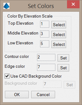
Color By Elevation Scale: These three colors are used for the Color By Elevation option. The program will interpolate between these colors for the color scale.
Contour/Edge color: These colors control the coloring for contours and triangle edges. Note that this does not affect the coloring of contour polylines that are loaded into the viewer, but only contours that are generated within the viewer.
Use CAD Background Color: When enabled, the background color of the 3D viewer will match the CAD background color. If this option is disabled, you can set a different background color.
| Control | Action |
|---|---|

|
Sets the drawing view to match the view shown in the 3D viewer window. |

|
Sets the view position and target position by coordinates
according to the below dialog. |
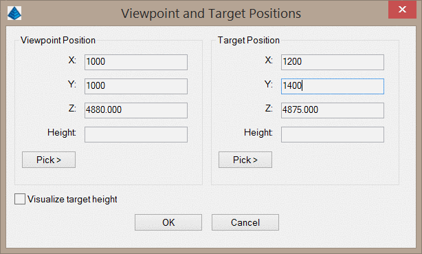
The positions can be entered in the edit boxes or you can use the respective Pick > button to pick a point in the drawing. The program will pick up the elevation of the surface for picked points and then the Height above the position can be entered. For example, to check sight distance the view position could be a point on a road at the driver's eye height and the target position could be the distance to check.
Saved Views:
This option allows for naming and saving a 3D
view for easy recall later. Named views can be selected from the
pull-down and the active view can be deleted from the
list.
Block Model Objects: This option has three choices when loading block model entities:
Shading Mode: When the Shading control is enabled, the rendering of the shaded 3DFACE entities (usually used to represent a surface model) will vary based on:
| Control | Action |
|---|---|
| Adds a single surface file to the 3D Viewer. You may also add
one or multiple surfaces to the viewer by right clicking on
"Surfaces" in the tree view. |
|
| Allows you to edit properties of the currently selected
entity. |
|
| Loads a 3DX file into the viewer. This files
contains all entities within a saved 3D View. |
|
| Save the entities in the 3D Viewer to a 3DX
file. |
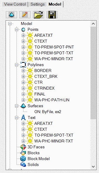
Within the "model" tab is a "tree-view" of the various entities
that comprise the view along with the listing of layers upon which
the entities are found. Each "branch" in the tree view may be
expanded by clicking the "+" symbol to the left of the branch.
Entities may be displayed (thawed), hidden (frozen), or edited by
right clicking the entity name and selecting the appropriate
option. The below dialog shows the properties of a surface that may
be edited.
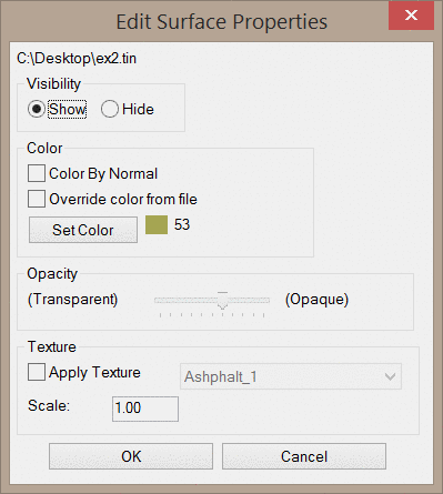
Visibility: This option toggles the visibility of the entity.
Color By Normal (Surfaces/Solids): When enabled, this option will color the surface/solid by the direction perpendicular to each face. This view can be useful for identifying particularly steep areas of the surface. The Color By Elevation option must be disabled to show the designated color.
Override color from file: When enabled, this option will override any color assignments and display the entity as a single color. The Set Color button below this option sets the color for the entity. The Color By Elevation option must be disabled to show the designated color.
Opacity (Surfaces/Solids): This option controls the opacity of the entity. A lower opacity results in increased surface transparency and is helpful for viewing sub-surface utilities such as Storm Sewer pipes and manholes.
Texture (Surfaces/Solids):
When enabled, the option colors the surface
with a texture such as grass or asphalt. The Scale of the
texture may be modified to enlarge or shrink the image
resolution.
Shading Mode (Solids): This
option controls which side of the 3D faces of the solid should be
shaded.
These controls are always displayed at the bottom of the
window.
| Control | Action |
|---|---|
|
The Clip Plane slider bar hides a portion of the view. Sliding the bar to the right will clip more of the view. This is helpful for producing quick "section" views of the data. |

|
This button takes a screenshot of the 3D Viewer. Several
different image file formats are supported including bmp, png, jpg,
xpm and gif. The image resolution and color depth may be set with
this option. |

|
This button exports the 3D Viewer to a PDF report with project
information. The default project information is set under Carlson Configure →
General Settings. The dialog that appears for this command is shown
below. |
| This button exports the 3D Viewer to a 3D PDF.
This function is further described in the to the 3D
Viewer to 3D PDF help article. Note that you must have access
to the CADNET module in order to use this command. |
|
| This button opens the help documentation you are
currently reading. |
|

|
Exit the 3D viewer window. |
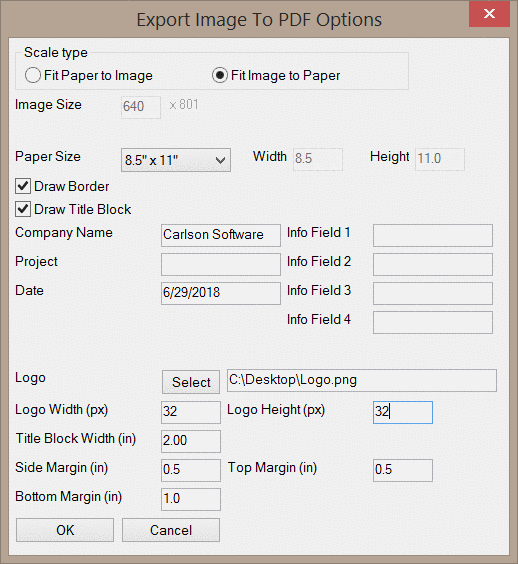
Scale Type: This option controls how the image and the paper will be scaled to match one another. When the Fit Paper to Image option is selected, you will be able to manually set the Image Size.
Paper Size: This option sets the size of the PDF.
Draw Border: This option toggles the addition of a border around the PDF.
Draw Title Block: This option toggles the addition of a title block in the PDF. Information such as the Company Name, Project, Date, and Logo will be included in the title block. The logo may be selected by clicking the Select button and the dimensions may be specified in pixel dimensions.
Top/Side/Bottom Margin: These values set the margins around the PDF in inches.
Pulldown Menu Location: View > 3D View
Keyboard Command: cube
Prerequisite: Entities to display