
Click Set and choose the file called "Carlson.fld" and Click OK
In this lesson, you will make a plat using field to finish techniques, with the help of the Startup Drawing Wizard.
1 Launch Carlson, or, if you are already in the program, select the File menu, and select New to start a new drawing. Save your existing drawing first, if you'd prefer. If you are asked to use a template, choose carlsonxx.dwt, where xx is the last two digits of the AutoCAD release that you are working with. For example, for AutoCAD 2008, you would select carlson08.dwt.
The first of several Startup Wizard dialog boxes appears. If the Startup Wizard does not appear, then go to the Settings menu, choose Configure and then select General Settings. In the General Settings dialog, click Use Startup Wizard in the upper-left and click OK. Then open a new drawing again.

Once in the Startup Drawing Wizard, click Set at the top of the dialog box, and enter in a new Drawing Name. Since this is Lesson 3, call the new drawing Plat3.
Verify that the other settings match the settings shown above, and click Next. You will see the Startup Wizard Data Files dialog. This dialog box is used to specify where to store data, and the existing point information source. Click the Set button to establish Plat3.crd as the new CRD file name.

Our source is the same file as in Lesson
2, Plat.txt. This is an ASCII file, so select Text/ASCII
File for the source of our Point data and click Next.
The Import Text/ASCII File dialog box appears. Click the Select
Text/ASCII Files button.Click Next.
In the next dialog box, titled Text File to Read, choose plat.txt from the "\Carlson Projects" folder, and then click Open.
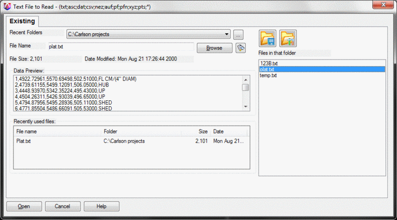
The Text/ASCII File Format dialog appears again, and the format of the points appears in the Preview Window, for verification, as shown below. Be sure that to the right of Draw Point, that Draw-Locate Pts is selected. Set the other options as shown. Click OK.

The points are then copied into the file Plat3.crd. If you repeat this exercise, and again use the file name Plat3.crd, you will be asked:
[O]verwrite w/new coordinates, overwrite [A]ll, or use number <55>: A (for all)
In either case, when you correctly complete the process, the following dialog box appears:

Then this Drawing Import Wizard dialog box appears:

Choose the Field to Finish option, and click Next.
A dialog box now appears with a warning that some codes have two descriptions.

The command is asking whether these codes are to be treated as two separate descriptions, or as one description that has a space in it. Choose the default (Split all multiple codes) to tell the command that codes with spaces are really two separate descriptions, and click OK.

Click Edit Codes and the following dialog loads

Click code Table Settings
Click Set and choose the file called "Carlson.fld" and Click
OK

Press Exit in the Field to Finish dialog & Exit in the Code
Table Dialog.
The Draw Field to Finish dialog box appears. Choose the options as shown here. Then click Additional Draw Options.
This displays a dialog box that provides many additional options, as shown below.

You want to draw all 1 through 54. Make sure the other options
are set as shown above. Click OK twice.
Error not gone any further
Draw Field to Finish now draws the points and linework. Draw Field to Finish saves you many manual steps. Your plat is shown below:

2 To understand how the above drawing was created, select Draw Field to Finish from the Survey menu. If you are prompted about Possible Multiple Codes, accept the default Split all multiple codes option and click OK. On the Draw Field to Finish dialog box, select the Edit Codes/Points button. This takes you to the Field to Finish dialog box.
The display window shows a list of point codes, such as IP for iron pin and FL for fence line, that are converted to special symbols and linetypes by Draw Field to Finish. For an example of how the codes are used, look at the sewer line running from point 52 to 53 to 54 (the southernmost point), which is based on a field code of MH. Select MH for Manhole as shown above, and then click Edit. The following dialog box is displayed.

Other codes have fewer attributes. LP is set only to draw a symbol and text (Light Pole), but not to draw linework. FL, for fence line, is set to draw linework but not corner symbols or points descriptions. A code's attributes depend on the entries in the Set Linetype, Set Symbol, Description and Entity Type options.
The "Carlson.fld" Field to Finish code table is provided with Carlson Software. This table shows one possible system, but with far too many codes for a field crew to remember. You can make your own table by choosing the Code Table Settings option from the Field to Finish dialog box, then choose the Set button at the top right. Then select the New or the Existing tab from the top of the Specify the Code Definition File dialog box, in order to create or select a different code table (.FLD) file.
Click Exit to dismiss the Field to Finish dialog box.
3 Use the Layer ID command, located under the Inquiry menu to verify the layers of the various plotted entities. Select Layer ID. Pick on the fence line, the road and the utility line, and notice the different layers (FENCE, EOP, UTILITY). You can also use Drawing Inspector under Inquiry to hover over linework to see their layer. You should study the layers in a drawing before deciding what to freeze and thaw. To reduce clutter on the screen, select the Layer Control command from the View menu (the appearance of this dialog box might vary from that shown below).

Freeze the PNTS layer, the SPOT layer, and the PNTELEV layer by turning the sun into a snowflake. To select multiple layers hold Ctrl, Then click OK.
4 Now you will do some drawing cleanup. Note that a single property line is drawn from point 8 to 9 to 10 and to 15. The chord from point 10 to 15 should be an arc. You will erase the segment from 9 to 10 and from 10 to 15, so that you can re-draw it, establish the tangent, then draw the arc and finish back at point 1.
From the Edit menu, select the Polyline Utilities > Remove Polyline > Remove Polyline Segment command.
Break polyline at removal or keep
continuous [<Break>/Continuous]: press Enter for Break
Select polyline segment to remove:
Pick the segment from 9 to 10, then the
segment from 10 to 15, then press Enter to end
To draw the correct polyline, use the 2D Polyline command under the Draw menu. If you prefer to type in the command, type 2dp which stands for 2D Polyline. If the Polyline 2D Options dialog box appears, accept the default values and click OK.
[Continue/Extend/Follow/Options/<Pick
point or point numbers>]: 9
[Arc/Close/Distance/Follow/Undo/<Pick point
or point numbers>]: 10
[Arc/Close/Distance/Extend/Follow/Line/Undo/<Pick point
or point numbers>]: A
[Radius pt/radius Length/Arc
length/Chord/Second pt/Undo/<Endpoint or point
number>]: 15
[Arc/Close/Distance/Extend/Follow/Line/Undo/<Pick point
or point numbers>]: 1
[Arc/Close/Distance/Extend/Follow/Line/Undo/<Pick point
or point numbers>]: press
Enter
Use the 4-Sided Building command (found under the Survey menu) you learned in Lesson 2 to create the other two sides of the shed, located in the upper middle of the screen, near point 17. The end result, except the house, is shown below:
5 Much of the text in the above drawing, such as tree sizes and types, the manhole text, and the light pole text, can be used in the final drawing. But some of the text, such as the text plotted for iron pins and poles, can be fully described in the Legend without the redundancy of plotting to the screen. If you use the Erase command to remove the iron pin and pole text, the entire point will be erased because the attributes are grouped with the point. Instead, use the Erase Point Attributes command under the Points menu.
Select attribute(s) to erase (Enter to end): pick the 3 poles and the 4 iron pins and then press Enter when complete
6 Next, you will use Extend by Distance command to create a building. The building will be less complex than the building you created in Lesson 2, but you will use the "t" and "c" options in addition to "l" for left and "r" for right. From the Edit menu, select the Extend > By Distance command.
Pick line or polyline to extend:
pick the western side of the small line
segment west of the 12" pine and north of the
driveway.
Enter or pick distance to Draw
(A,B,C,E,I,L,M,N,O,P,R,S,T,U,Z,?,Help): T50
"T" or "t" means "total" distance or "to" the distance - so extend
"to" 50 feet total.
Enter or pick distance to Draw
(A,B,C,E,I,L,M,N,O,P,R,S,T,U,Z,?,Help): L62.5
Enter or pick distance to Draw
(A,B,C,E,I,L,M,N,O,P,R,S,T,U,Z,?,Help): L35
Enter or pick distance to Draw
(A,B,C,E,I,L,M,N,O,P,R,S,T,U,Z,?,Help): L30
Enter or pick distance to Draw
(A,B,C,E,I,L,M,N,O,P,R,S,T,U,Z,?,Help): R15
Enter or pick distance to Draw
(A,B,C,E,I,L,M,N,O,P,R,S,T,U,Z,?,Help): C
Enter or pick distance to Draw
(A,B,C,E,I,L,M,N,O,P,R,S,T,U,Z,?,Help): press Enter
In Extend by Distance, the "T" option (for total distance) solves the dilemma of making an existing line of unknown length extend to an exact known length.
7 Use the Twist Screen command to better position the plat on the sheet. Not every drawing can be plotted "due North." Sometimes the plat needs to be oriented so that property lines and important features run nearly left-to-right or top-to-bottom on the plotted page. In this drawing, you want the western line from point 8 to point 9 to run left-to-right on a sheet that will be plotted in landscape style (longer left-to-right than top-to-bottom). Under the View menu, select the Twist Screen > Line, Polyline or Text command.
Pick a line, polyline or text to make horizontal: pick the western line from point 8 to point 9, closer to point 9
Now the drawing appears as shown below:

Notice that the north indicator (referred to as the USCICON, if shown) at the lower left displays the orientation. The benefit of the Twist Screen options are that coordinates of points and directions of lines have not changed. In other words, only the orientation of the data on the screen has changed.
8 Now select Twist Point Attributes, under the Points menu, to twist the point descriptions and point numbers back to a left-to-right rotation.
Twist by [<Twist
screen>/Azimuth/Entity segment/Follow polyline]?
press Enter
Enter angle relative to current twist screen
<0.0>: press Enter
Select points from screen, group or by point
number [<Screen>/Group/Number]? press Enter
Select Carlson Software points.
Select objects: ALL, and then press
Enter twice
The points then twist back orthogonal to the screen, reading once again from left-to-right.
9 The remaining descriptions associated with the points can be used in the final drawing, but they should be moved slightly for a better appearance. For example, the tree descriptions would look better if they were not inside the tree canopies.
Under the Points menu, select Move Point Attributes - Single. The steps of the command are:
Select attribute(s) to move (Enter to
end): pick an attribute to
move
Displacement: pick the new location for the attribute
Rotation: pick
the new orientation for the attribute or press Enter to keep the existing orientation
Then the command repeats. Notice how the text "ghosts" as it moves, which helps you place it in the best position. Try to duplicate this result:

10 Because of the earlier Twist Screen command, the E's in the electric utility polyline are upside down. From the Edit menu, select the Text > Flip Selected Text command.
Select the text to flip.
Select objects: pick the upside down
E's individually and then press Enter (see above image)
11 We wish to apply building dimension labels to the exterior of the building created earlier. From the Annotate menu, select the Survey Text > Survey Text Defaults command and set the Exterior option as shown below:

Click OK when complete. From the Annotate menu, select the Survey Text > Building Dimensions and pick on the house. If the text overwrites the inside corner of the house, use the Move command (under the Edit menu, or type M for Move at the command prompt) and move the 30' dimension beneath the line.
12 To automatically annotate bearings and distance, as well as arcs, select the Auto Annotate command from the Annotate menu. When the dialog box appears, under the Lines tab, select the options you would like to use so that the bearings and distance labels appear as you would like. Then pick the three polylines that fully define the perimeter: the fence line, the polyline containing the arc, and the lower polyline, which is still the western polyline although you have twisted the screen so that it runs along the lower portion of the drawing. Use the Move command to move the bearing and distance labels to avoid overwriting other features.
When you move the lower distance label, 404.90' to the left, you want to move perfectly level to the screen, since this was the line you used to twist the screen, and it runs perfectly left-to-right. To do this, press the function key F8 to activate Ortho. Then pick 404.90' and move it to the left, picking its final position. Repeat this for the S 17°05'38" E bearing. After you move these items, press F8 again to turn off Ortho. Sometimes you will load a drawing from another client or source, and the Ortho setting has been left on. This may initially confuse you during the Move commands. Press F8 to deactivate Ortho. Notice that F8 works even with Twist Screen active.
13 Auto Annotate may center the arc annotation above and below the arc, which may cause the arc data to overwrite the surveyed edge-of-pavement (EOP) polyline. As needed, you may want to erase the arc annotation, and use the Annotate > Annotate Arc > Label Arc command to better control the placement of the arc annotation.
If needed, erase selected portions of the arc annotation. At the command line, enter E for Erase.
Select objects: enter WP and then press Enter
First polygon point: pick initial point of a polygon
Specify endpoint of line or [Undo]:
pick subsequent points as shown and then
press Enter twice when the selection set is complete
There is no "close" option for window polygon and crossing polygon
selections.

For the new annotation, under the Annotate menu, select the Annotate Arc command, then the Label Arc option. Then select the arc from the screen. The Label Arc Settings dialog box appears:

You want to locate the arc text inside the arc, on positions 1 and 2. Position (Row) 1 is just under the arc, and 2 is under 1. Be sure they are both Inside. Fill out the dialog box as shown above and click OK.
The new arc text might overwrite the 8" Pine, so, if it does, use the command Move Point Attributes - Single, in the Points menu, to relocate the 8" Pine description.
With the annotations placed in new positions, your drawing should be similar to the one shown below. Move your annotations to match this drawing.

14 To label
the area of the lot, first select the Area Defaults command from the
Area/Layout menu. Set Sq. Feet (s.f.) to the nearest whole unit (no
decimals) with a Text Size of 0.100 and Acres to 2 decimal places
with a Text Size of 0.100. Then click OK to exit the dialog box.
Select the Area by Lines &
Arcs command from the Area/Layout menu, and pick the three
polylines individually that define the property perimeter. Press
Enter and locate the text to the left of the 12" Pine.
15 Before completing the final formatting of your drawing, you need to do some minor cleanup, using procedures you learned in Lesson 2.
You don't want point 16, the PL point, to show in the final drawing. Use the Drawing Inspector command, under the Inquiry menu, to verify the layer of point 16, which should be MISC. Freeze MISC using the Freeze Layer command on the View menu, and pick point 16. Freeze the point numbers using the Layer Control command on the View menu, and freeze the layer PNTNO.
16 To insert an A1, 8-1/2 x 11 border and title block, with the orientation landscape (not portrait), select the Title Block command from the Settings menu. You will see this dialog box.

Be sure these above selections match your own. Click OK. For the insertion point, select a point at the very lower-left of the screen, so that your drawing plan entities fit inside the border and somewhat nearer to the top. Pick your screen location. You will then be prompted for the attributes of the title block. Fill them in and click OK.

If you prefer, you can use the Move command, pick the title block and two border perimeters, and move them. Never move the drawing, because you will change the coordinates if you do. Move the drawing only if changing the coordinate locations does not matter.
17 From the Annotate menu, select the Draw Legend command. Select the Existing tab and choose the .lgd file that you saved in Lesson 2 and click Open. Then select Draw and OK to close out the dialog boxes that follow, and then click Exit.
Pick an upper-left location point in the available space to the lower-left of the plat. If you did not save a legend in Lesson 2 (or you skipped Lesson 2), follow the steps in that lesson. Use the Resize Point Attributes command, under the Points menu, and scale up the oak tree symbol in the Legend by a factor of 1.5.
From the Annotate menu, select the Survey Text > Survey Text Defaults command. Change the Offset Dimension Text - Text Alignment to Horizontal (it may have been set to Parallel in Lesson 2). Click OK. From the Annotate menu, select the Survey Text > Offset Dimensions command and pick the lower right corner of the building, and then the lower-most property line (in the current twist screen position). This labels the offset dimension horizontal to the current twist screen.
From the Annotate menu, pick the Draw North Arrow command and find and select the north arrow symbol that is shown in the figure below. Change the Symbol Size Scaler, if necessary. Click OK. Then pick an appropriate location and press Enter. Note how the arrow draws due north, respecting the twist screen.
From the Annotate menu, pick the Draw Barscale command and pick a location near the lower-left portion of the drawing.
Your drawing should now look similar to this:

18 Select the Hatch command from the Draw menu.

Select the SOLID pattern from the Pattern, and then click the Add: Select Area button. Pick an internal point in the house and the shed, and press Enter, then OK.
19 To offset the EOP polyline, first try using the Standard Offset command under Edit > Offset, and try offsetting the edge-of-pavement polyline that runs roughly parallel to the sewer line. You will see an error message because that object is a 3D Polyline, created by the Draw Field to Finish command.
To offset a 3D Polyline, you must use a command specifically
designed to offset 3D Polylines. From the Edit menu, select the
3D Polyline Utilities >
Offset 3D Polyline
command. Enter
the offset method as Interval, press OK.
Vertical/<Horizontal offset amount>: 30
Percent/Ratio/Vertical offset amount
<0>: press Enter
Select a polyline to offset:
pick the EOP polyline
Select side to offset: pick out and away from parcel for the other side
of the road
20 Before you add a title to the drawing, create a text style for the title. From the Draw menu, select the Text > Set Style command.

Click New and name the style TITLE. Choose the font named romant.shx and then change the oblique angle to 10° as shown. Click Apply, and then click Close. Now, to create the title, type Dtext at the command line. Make sure that TITLE is the current text style.
Specify start point of text or
[Justify/Style]: C
Specify center point of text:
pick a point near the top-right of the
screen
Specify height <8.00>:
20
Specify rotation angle of text
<E>: pick a point to right of
first point with <Ortho on>, dynamically stretch
right
Text: Farmer
Survey
Text: August 13,
2006
Text: press Enter
twice
From the Edit menu, select the Text > Text Enlarge/Reduce command. Enter a Scaling Multiplier of .8 and pick the date you just entered.
21 Verify your drawing scale through the Settings > Drawing Setup command. Your drawing should have a scale of 100 with a Text Plot Size of 0.08. Change the Text Plot Size to 0.06 to shrink the building labels we are about to place. From the Draw menu, select the Leader > Leader with Text command and label the house "2-Story", "Farm House" (2 lines of labeling).
Options/Size/Pick Arrow Location:
pick near or on the left side of the
house
To point: pick
off to the left
Next point (Enter to end): press Enter
Text: 2-Story
Text: Farm
House
Text: press
Enter
Pick anywhere on the leader. You should see two grip squares (usually blue, referred to as a cool grip), one on the left side and one of the right side. Pick on the right grip nearest the house (it should turn red, referred to as a hot grip). Move your cursor. Note how the arrow moves. Pick again for the new location and note how the arrowhead and leader are now located and angled to your specifications.
22 Select the Triangulate & Contour command from the Surface menu. On the Triangulate tab, turn off Write Triangulation File. The Contour tab of dialog box should be filled out as shown below:

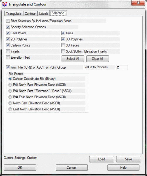
Click on the Selection tab and fill out to match the following:
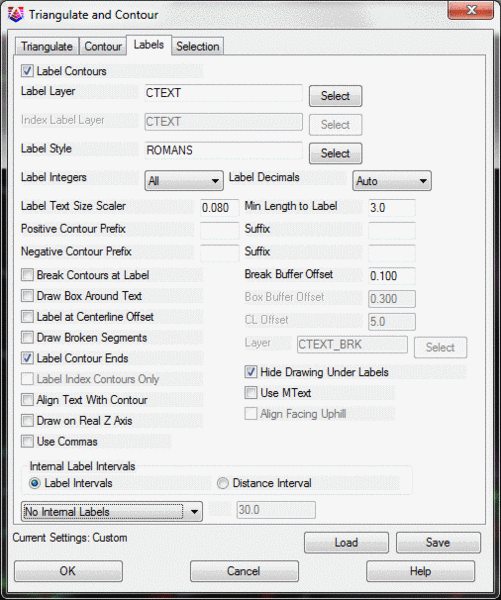
Click on the Labels tab and match the following dialog:
Click OK.
Select the Inclusion perimeter polylines or
ENTER for none.
Select objects: press
Enter
Select the Exclusion perimeter polylines or
ENTER for none.
Select objects: pick the house and the
shed
Since these objects have now been filled, the selection may be a
little tricky. We could (actually should) have placed the solids on
their own layer and froze the layer before beginning the contour
command. But we can use the fact that Carlson is filtering the
objects to get around the problem. When prompted to select the
objects, issue the C (for crossing) option and then pick a box that
crosses the edge of the filled polylines. Carlson will accept the
polyline but reject the fill.
Select the points and breaklines to
Triangulate. select a right-to-left
window of the property
A right-to-left selection behaves as a crossing, which means that
any object that is touched by the window or included inside the
window is selected. A left-to-right selection is a window
selection, which means that only objects that are fully enclosed by
the window are selected.
Select objects: pick Window location
Other corner: pick other location
Select objects: press Enter to end
Pick the coordinate file that contains the points, plat3.crd, and
click Open.
Reading points...
Range of Point Numbers to use
[<All>/Group]: press
Enter
Wildcard match of point
description<*>: press
Enter
If the triangulation lines and faces were drawn, freeze them now. The final drawing will look similar to this:

This completes the Lesson 3 tutorial: Field to Finish for Faster Drafting.