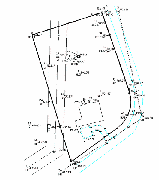
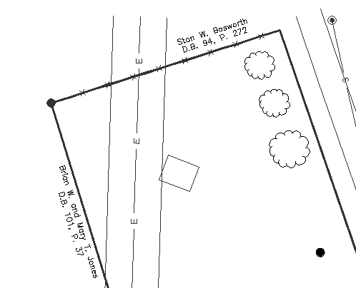
In this lesson you will draw out a plat of a single lot, using Carlson drafting techniques. You will make the plat from an ASCII file of points named Plat.txt.
1 Click the icon for Carlson. You may be presented with a Startup Wizard dialog box, as shown below:
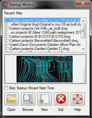
You will use the Wizard in Lesson 3 to perform a series of commands to begin a drawing. In this lesson, however, you will enter the commands individually, so that you can see what each one does.
If you see the Startup Wizard dialog box, and you don't want to see it again, click the Skip Startup Wizard Next Time option in the dialog box above. Make sure the other settings are as shown above and click Exit.
Another way to turn off the Wizard is to click it off within the Configure > General Settings command, found under the Settings menu. You will open this General Settings dialog box now.
2
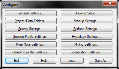
On the Settings menu, click Carlson Configure to
display the following menu:
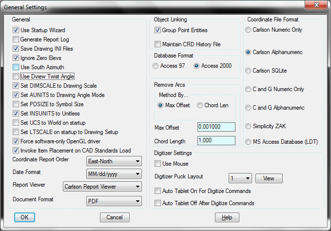
Choose Numeric Only to store points in numeric form. This produces point numbers such as 1, 2, 3, 10 and 11. If you selected Alphanumeric, then you could have point numbers like 1A, 1B, 1C, HUB5, CTRL, SS10, etc. There is a slight speed advantage to working with purely numeric point numbers. The highest numeric point number allowed is 99999. Regardless of format, point numbers are stored in a file that has a .crd extension. There is no limit to the number of points in an alphanumeric coordinate file. In anticipation of Lesson 3, click on the Use Startup Wizard option. Click OK at the bottom of this dialog box.
Now we want to set the data path. Another of the Configure sub-options is Project/Data Folders. Click this option and you will see this dialog box.
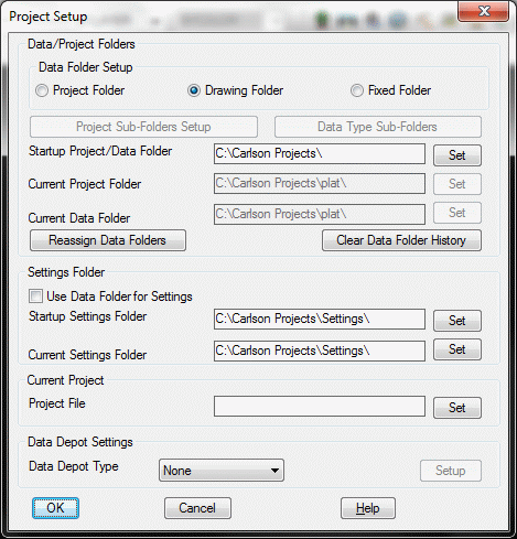
For this lesson, you will keep it simple. Click on Fixed Folder at the top. Notice the Current Data Folder section at the bottom. This specifies where data files, such as .crd files in this case, are to be stored. Set the folder to C:\Carlson Projects\. Click OK. You are now back to the Configure main dialog.
3
Select Drawing
Setup from the Configure main dialog box.
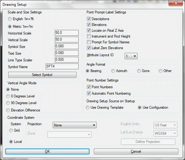
The scale acts as a multiplier on all text annotation. For example, 100 * Text Plot Size (0.08) = 8 (text height of 8 units). The Text Plot Size is the effective height, in inches, that the text will appear when plotted at the Horizontal Scale (here 100).
Bearings and Distances, Legends, Title Blocks, and Point Symbols will size up or down on the basis of the Horizontal Scale set within Drawing Setup. Set the Horizontal Scale to 25. Then click OK to exit Drawing Setup. Then click Exit to close the Configure dialog box.
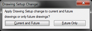
If prompted for Drawing Setup Change, click on the
Current and Future button.
If you have not already saved your drawing, now is a good time to do it. Use the Save command on the File menu, and call the file Lesson2.dwg.
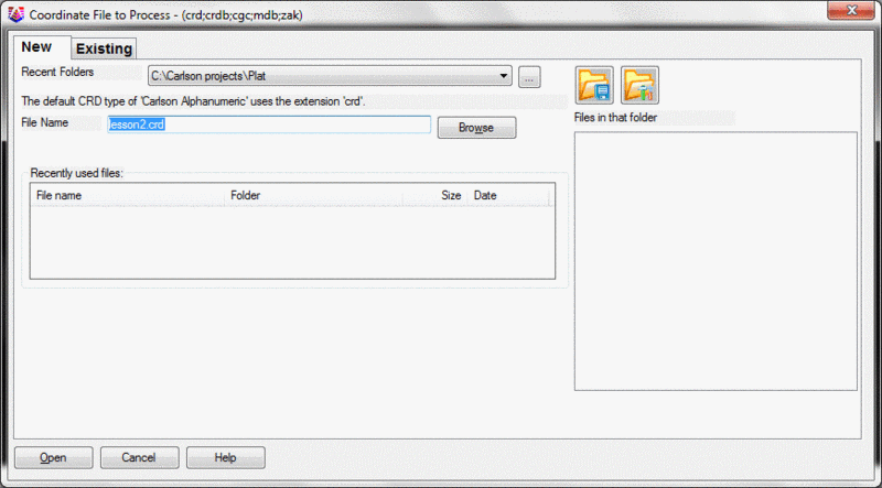
4 Next, you will import the ASCII file called Plat.txt and store the points in a Coordinate file called Plat.crd. However, since you are in a new drawing, you have not yet set a coordinate file to store the points in. You must have a Carlson coordinate file (.crd) open and established as the container for your points.
So, under the Points menu, select the command Set CooRDinate File to display a dialog box. Click the New tab, as shown here. To the right of File name enter Plat and click Open. You have now created the required .crd file.
You are now ready to import the points. This time, under the Points menu, select Import Text/ASCII File to display the Text/ASCII File Format dialog box, as shown below. Click the Select Text/ASCII Files button and then choose Plat.txt listed on the right. It is found in the default data folder (C:\Carlson Projects). Click Open.
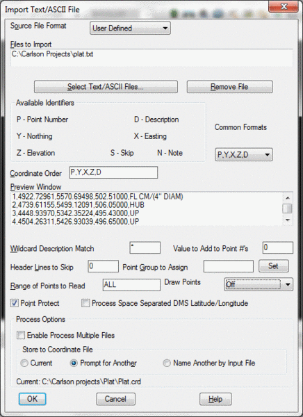
Plat.txt is an ASCII file containing 54 points in the form of Point Number, Northing, Easting, Elevation and Description. The format of the points appears in the Preview Window. The format is: Point (P), Northing (Y), Easting (X), Elevation (Z), Description (D), or, in short, P,Y,X,Z,D. You must match this format in the Coordinate Order. If you don't see P,Y,X,Z,D in the Coordinate Order box, then select that format from the Common Formats option. Or, you can type the list directly into the Coordinate Order box. Make sure that Draw Points is set to Off.
Click OK. The points will be saved and stored in Plat.crd. A confirming dialog appears as follows:
Click OK.
5 Choose the List Points command under the Points menu.
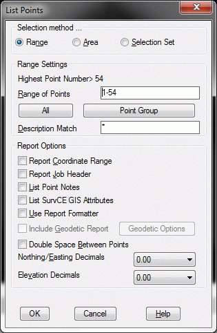
The List Points dialog box will typically default to the full range of points (ALL), which is 1 through 54 in this exercise. You can control the decimal places for the Northing/Easting and the Elevation of the points in the lower portion of the dialog box. Click OK and the settings shown above result in the report exhibited below in the Standard Report Viewer:
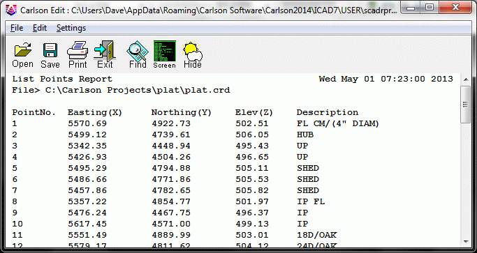
Exit the report by selecting the Exit icon at the top of this report viewer box, or by clicking the X in the upper right of the window.
6 Select the Draw-Locate Points command on the Points menu to draw the points on the screen.
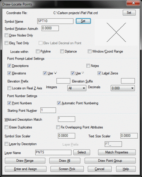
Enable the Descriptions option as shown above. Also in the figure shown above, the current Symbol Name is showing as SPT10, which stands for Survey Point symbol 10. SPT10 is an X, shown in the symbol display window. You can select a different default symbol using the Point Defaults command on the Points menu.
In this exercise you will change the Symbol Name to null, or symbol 0, listed as SPT0 (in effect, no symbol). Later, you will add official property corner and utility symbols. Although you are working without a default symbol, there will always be a "dot" or a node at the correct insertion point of each point number.
At the top click Set You will see the following dialog box:
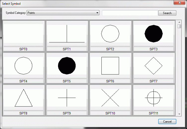
Note that the scroll bar at the right of this Select Symbol dialog box leads to more pages of symbols. Click the blank SPT0 point symbol option.
When you select a symbol, you automatically return to the
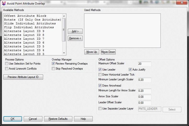
Draw-Locate Point dialog box. Click the Fix Overlapping Point
Attributes box if this is not already checked. Click Draw All and
the following dialog will display. The Avoid Point Attribute
Overlap dialog uses different adjustment methods, such as moving
attributes and creating leader lines, to fix conflicts with the
point labels. Pick Cancel for now so we can view these
conflicts.
Here you have the rather busy drawing shown below:
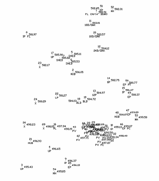
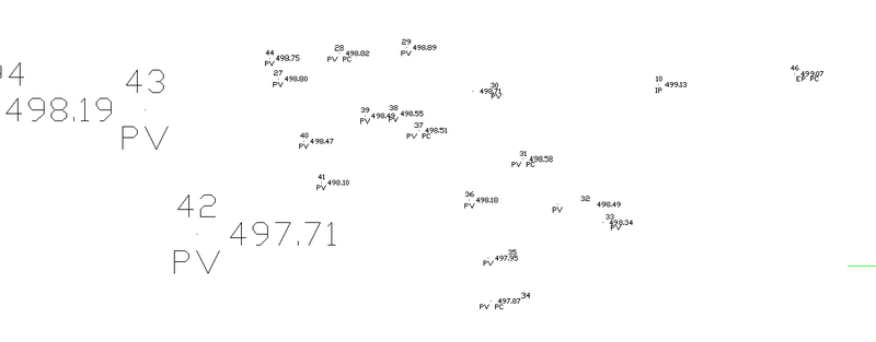
7 You will now be using the Resize Point Attributes command on the Points menu. Notice how the lower-right corner of the drawing is very congested, with many overlapping point attributes. You can specify a window containing these points and scale them down by a factor of 0.4. For Scaling Multiplier, you will enter 0.4. When you are prompted to Select Carlson Software points, you will enter WP for Window Polygon and make a polygon around the congested area. Press Enter when you have surrounded the points with the polygon as shown below. Here is the command line sequence, along with the responses you will enter, after clicking Scale Point Attributes:
Method for resizing
[<Scale>/Absolute]? Scale
Scaling Multiplier <0.500>:
.4Scale symbols
only, point labels only or both
[Symbols/Labels/<Both>]? press
Enter
Select points from screen, group or by point
number [<Screen>/Group/Number]? press Enter
Select Carlson Software points.
Select objects: wp
First polygon point: start creating your polygon
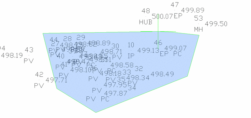
Once this polygon is complete, you are again prompted to select objects. Press Enter. The following shows the scaled points.
8 Next, you will prepare for drawing linework by setting the current layer. You should draft linework and symbol work in designated layers. In this example, you will put linework and symbol work in a layer named Final. (You could put property linework in the Final layer and utility linework in the Utility layer, but, for now, you will put all linework and symbols in the layer Final.) To pick the current working layer, select the Layer Control command from the View menu.
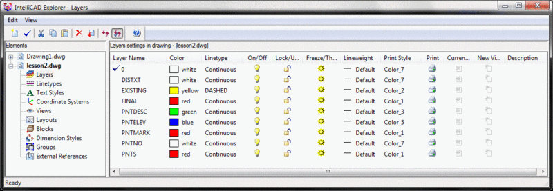
Click Final. Right click, select Current and close the Layer control.
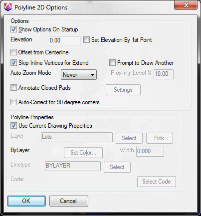
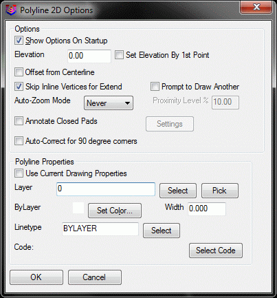
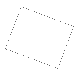
9 The 2D Polyline command allows you to enter point numbers to draw a line. First, connect portions of the property line. Select the 2D Polyline command on the Draw menu. A dialog box might appear. If it does, accept the defaults and click OK.
This creates a polyline. Keep this as a separate polyline because later you will turn this back lot line into a fence line. Now, connect some of the other property lines. Repeat the 2D Polyline command. You can press Enter to repeat the command, or you can select it from the Draw menu. Connect points 8 through 10, and start an arc, by entering as follows:
[Continue/Extend/Follow/Options/<Pick
point or point numbers>]: 8-10
[Arc/Close/Distance/Extend/Follow/Line/Undo<Pick point
or point numbers>]: a
[Radius pt/radius Length/Arc
length/Chord/Second pt/Undo/<Endpoint or point
number>]: 15
[Arc/Close/Distance/Extend/Follow/Line/Undo<Pick point
or point numbers>]: 1
[Arc/Close/Distance/Extend/Follow/Line/Undo<Pick point
or point numbers>]: press
Enter to end the command
This creates the full lot, with the arc coming off point 10 on a tangent. The line from 15 to 1 is not guaranteed to be tangent to the previous arc.
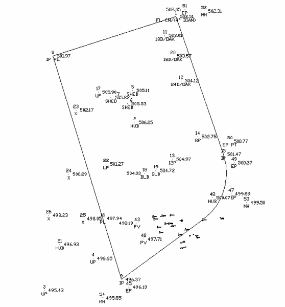
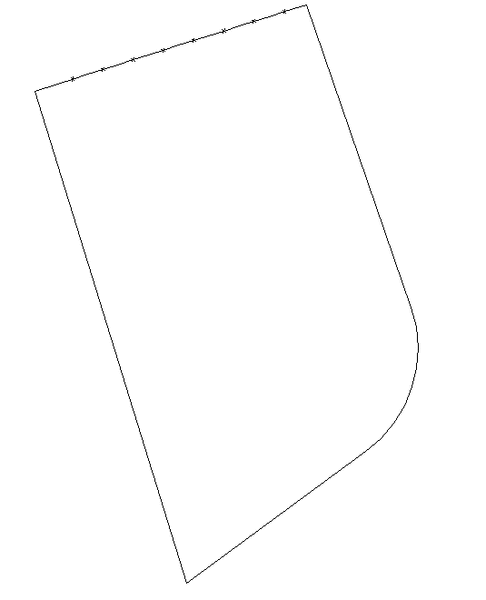
You should have the following linework at this point:
10 You will now create a fence line on the polyline you drew from points 1 to 8.
Now, choose the Line Types, Change Polyline Linetypes command on the Annotate menu and select the Change Polyline Linetype command. The Line Types command creates polylines that respond as one entity when selected.
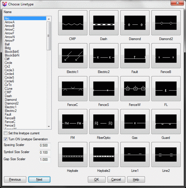
Choose the Fence_S option (the solid fence line).Press
OK.
When prompted to Select Objects, pick the polyline you created from points 1 to 8. Press Enter to end selection. Notice in the dialog box above that the current Line Type Scaler, governing spacing, should be 0.5 (inches) and the Text (height) Scaler is 0.1. If your settings are different, you may want to Undo (by entering U for undo) the fence line and select the Annotate Defaults command on the Annotate menu, and set these items to match the example.
On the View menu, select the Isolate Layers command, pick the property line, and press Enter. Here is the result:
11 Next, you will connect up the edge of pavement. Select the 2D Polyline command under the Draw menu. Again, a dialog box might appear as shown below. If it does, make sure that the options selected are the same. In the future you can choose not to see this box.
[Continue/Extend/Follow/Options/<Pick
point or point numbers>]: 45-47,49-51
Press Enter at the next prompt to exit the command and create the
road. Press Enter one more time. Note how you can separate range
entries using a comma.
12 To smooth the edge of the road, select the Polyline Utilities command on the Edit menu, and select Smooth Polylines.
Enter the looping factor (1-10)
<5>: press Enter
Enter the offset cutoff <0.05>:
press Enter
Reduce polylines before smoothing
[Yes/<No>]? press
Enter
Select polylines to smooth.
Select objects: pick the edge of road
polyline
Select objects: press Enter
13 To offset the smoothed edge-of-road polyline by 24 feet to make the opposite edge of the road, Select the Offset > Standard Offset command on the Edit menu.
Specify offset distance or
[Through/Erase/Layer] <Through>: 24
Select object to offset or [Exit/Undo]
<Exit>: pick the edge-of-road
polyline
Specify point on side to offset or
[Exit/Multiple/Undo] <Exit>: pick to the right of the polyline
Select object to offset or [Exit/Undo]
<Exit>: press Enter to
end the command
Now, select the Isolate Layers command again from the View menu, pick on any of your linework, and only the entities on the picked layers are displayed.
Select the Restore Layers command from the View menu to recover your points. Experiment with the "cadence" of Isolate and Restore Layers. Select Isolate Layers, pick the layers to isolate, and then press Enter twice. Then select Restore Layers.
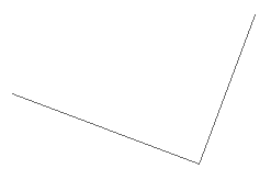
14 Next, you will draw the shed. Select the 2D Polyline command on the Draw menu. To draw a two-sided shed, connect points 5 through 7 as follows:
[Continue/Extend/Follow/Options/<Pick point or point numbers>]: 5-7 press Enter twice
This produces the 2-sided building shown here:
Select the 4 Sided
Building command on the Survey menu. Turn the 2-sided
she
d into a 4-sided shed as follows:
Options/<Pick a line or polyline>: Pick the shed
Now your 2-sided building looks like this:
15 Focus your attention on the area of tightly spaced points with point numbers ranging from 27 to 44. This is the driveway and paving area. In the case of the driveway, assume that the surveyor who collected the points shot in 3-point arcs. They came up to a PC, shot a point on the arc, and finished up at the PT.
On the View menu, select the Window option, and pick a lower left and upper right point that windows the driveway area. If you wish to use the View > Previous command to zoom out, then use View > Window to zoom in again.
Select the 2D Polyline command under the Draw menu, and walk the
polyline through the two arcs as follows:
[Continue/Extend/Follow/Options/<Pick
point or point numbers>]: 27
[Arc/Close/Distance/Follow/Undo/<Pick point
or point numbers>]: 28
[Arc/Close/Distance/Extend/Follow/Line/Undo/<Pick point
or point numbers>]: A
[Radius pt/radius Length/Arc
length/Chord/Second pt/Undo/<Endpoint or point
number>]: S
Use S for 3-pt arcs.
Second point or point number:
29
Endpoint or point number: 30
[Arc/Close/Distance/Extend/Follow/Line/Undo/<Pick point
or point numbers>]: 31
[Arc/Close/Distance/Extend/Follow/Line/Undo/<Pick point
or point numbers>]: A
[Radius pt/radius Length/Arc
length/Chord/Second pt/Undo/<Endpoint or point
number>]: S
Second point or point number:
32
Endpoint or point number: 33
[Arc/Close/Distance/Extend/Follow/Line/Undo/<Pick point
or point numbers>]: press
Enter
In the above exercise you started at point 27, went to the PC at
point 28 and inserted a 3-point arc through points 29 and 30. You
proceeded on a tangent direction to point 31, which was another PC,
then completed a 3-point arc through points 32 and 33, and ended.
Now, connect up the basketball court area. Select the 2D Polyline command under Draw, or
press Enter to repeat the previous command.
[Continue/Extend/Follow/Options/<Pick
point or point numbers>]: 27
[Arc/Close/Distance/Follow/Undo/<Pick point
or point numbers>]: 44
[Arc/Close/Distance/Extend/Follow/Line/Undo/<Pick point
or point numbers>]: 43-39 (you can
enter "backwards" ranges)
[Arc/Close/Distance/Extend/Follow/Line/Undo/<Pick point
or point numbers>]: A
[Radius pt/radius Length/Arc
length/Chord/Second pt/Undo/<Endpoint or point
number>]: S
Second point or point number:
38
Endpoint or point number: 37
[Arc/Close/Distance/Extend/Follow/Line/Undo/<Pick point
or point numbers>]: 36
[Arc/Close/Distance/Extend/Follow/Line/Undo/<Pick point
or point numbers>]: A
[Radius pt/radius Length/Arc
length/Chord/Second pt/Undo/<Endpoint or point
number>]: S
Second point or point number:
35
Endpoint or point number: 34
[Arc/Close/Distance/Extend/Follow/Line/Undo/<Pick point
or point numbers>]: press
Enter
Shown below is your drawing to this point.
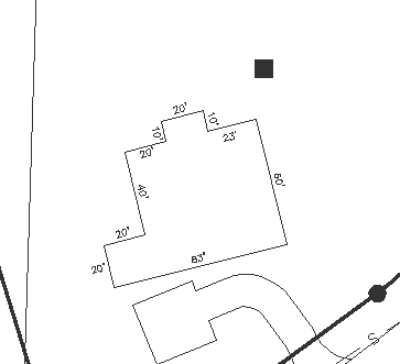
16 Next you will make a building footprint. Points 18 and 19 are two shot corners of a building. Assume that the surveyors taped the main house, going clockwise from point 18, as follows: 10'L, 20'R, 40'L, 20'R, 20'L, 83'L, 60'L, 23'L, 10'R.
You can easily enter these "jogs" in the building using the Extend by Distance command. If you are zoomed in on the driveway, use View > Zoom > Zoom Out, and then View > Pan to focus on the building north of the driveway. Now use the 2D Polyline command on the Draw menu to draw a line from 18 to 19.
Pick point or point numbers:
18
Undo/Arc/Length/<Pick point of point
numbers>: 19, then press Enter
twice to end
From the Edit menu, select the Extend > By Distance command.
Pick line or pline to extend:
pick the building line closer to point
18
This makes the arrow point toward 18 rather than 19. Now you can go
clockwise:
Enter or pick distance to Draw
(A,B,C,E,I,L,M,N,O,P,R,S,T,U,Z,?,Help): L10 (lower case "l"
and "r"
work also)
Enter or pick distance to Draw
(A,B,C,E,I,L,M,N,O,P,R,S,T,U,Z,?,Help): R20
Enter or pick distance to Draw
(A,B,C,E,I,L,M,N,O,P,R,S,T,U,Z,?,Help): L40
Enter or pick distance to Draw
(A,B,C,E,I,L,M,N,O,P,R,S,T,U,Z,?,Help): R20
Enter or pick distance to Draw
(A,B,C,E,I,L,M,N,O,P,R,S,T,U,Z,?,Help): L20
Enter or pick distance to Draw
(A,B,C,E,I,L,M,N,O,P,R,S,T,U,Z,?,Help): L83
Enter or pick distance to Draw
(A,B,C,E,I,L,M,N,O,P,R,S,T,U,Z,?,Help): L60
Enter or pick distance to Draw
(A,B,C,E,I,L,M,N,O,P,R,S,T,U,Z,?,Help): L23
Enter or pick distance to Draw
(A,B,C,E,I,L,M,N,O,P,R,S,T,U,Z,?,Help): C to close the figure
Enter or pick distance to Draw
(A,B,C,E,I,L,M,N,O,P,R,S,T,U,Z,?,Help): press Enter to end
17 Next, you will complete the linework for the sewer line and the electric utility line. Use the View > Extents command so you can see all your points.
The sewer line runs from points 52 to 53 to 54. Select the 2D Polyline command from the Draw menu. To create the sewer line, enter the following:
[Continue/Extend/Follow/Options/<Pick point or point numbers>]: 52-54, press Enter twice to end
You will next annotate the sewer polyline using the Change Polyline Linetype command, but first you must set the default spacing for the annotation. Select the Annotate Defaults command on the Annotate menu. The following dialog box appears.
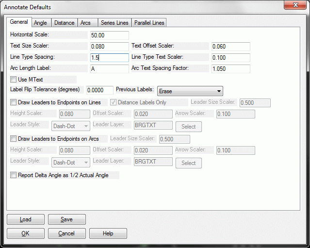
Change the Line Type Spacing to 1.5 and click OK. This will label "S" on the sewer line every 1.5" at the current scale (1"=50').
To annotate the sewer line with an S, select the Line Types command on the Annotate menu, and then choose Change Polyline Linetype. Within the dialog box, click Next twice, select the Sewer linetype from the list, and then select the sewer polyline that runs next to the road. The polyline will be annotated.
Next, create the electric utility line, which runs from point 3 to point 4 to point 17. Select the 2D Polyline command on the Draw menu.
[Continue/Extend/Follow/Options/<Pick
point or point numbers>]: 3
[Arc/Close/Distance/Follow/Undo/<Pick point
or point numbers>]: 4
[Arc/Close/Distance/Extend/Follow/Line/Undo/<Pick point
or point numbers>]: 17
[Arc/Close/Distance/Extend/Follow/Line/Undo/<Pick point
or point numbers>]: press Enter
twice to end
No points were taken beyond point 17, due to obstructions from the various setups in the field. So you must extend the polyline from point 17 to beyond the property. Under the Edit menu, choose Extend, then By Distance. Pick on the electric utility polyline near point 17. Then pick beyond the property. Press Enter to end
Before you annotate the electric utility line, you must offset it 25' on both sides, for a 50' total right-of-way. You will do this using Standard Offset. Select the Offset > Standard Offset command under the Edit menu. Enter the offset distance of 25. Pick the electric utility polyline and then pick to one side for the first offset. Repeat for the other side, by first picking the electric utility polyline, then picking the other side for the offset. Press Enter to end.
Now annotate the central electric line with an E by selecting the Line Types command on the Annotate menu, and then choose Polyline to Special Line. Choose the Electric linetype, which appears on the third page of linetypes. Then select the electric utility polyline to annotate it, and press Enter.
18 Next, make the Property lines bold. Under the Edit menu select Polyline Utilities > Edit Polyline and then select Change Polyline Width.
New Width <0.0>: 1.5
Select objects: Pick once for the
fence line portion and once for the remaining property
lines.Select objects: press Enter to end
19 To add color and improve layer management, make a layer for your road and driveway. Select the Layer Control command on the View menu.
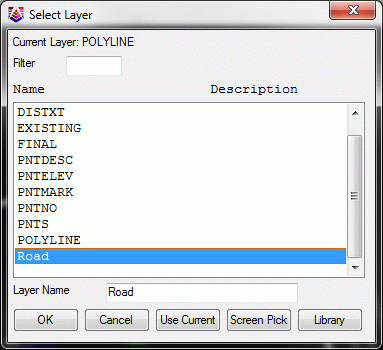
Click the New Layer button, and enter the name "Road" for the new layer. Choose the color Cyan by clicking the color square to the right of the layer name. Close the dialog.
On the View menu, select the Change Layer command.
Select entities to be changed.
Select objects: Pick all
driveway and road entities and press Enter
Specify new layer [Name/<pick
entity>]: N
This brings up the dialog box shown below. Select ROAD and click OK.
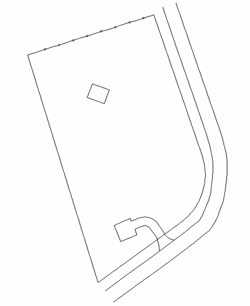
Your linework is now complete and is shown below:
20 You will add symbols for trees, property corners, manholes and a light pole.
Start with the trees. Points 11, 12, and 20 are oak trees of different sizes, and point 14 is a pine tree. Use symbol 61 for the deciduous oak trees and symbol 53 for the pine tree. On the Draw menu select the Symbols > Insert Symbols command. The following dialog box appears.
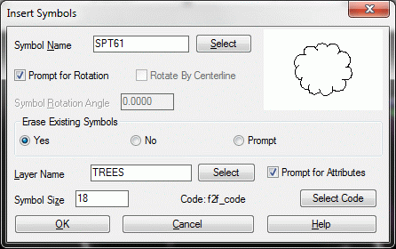
Click the Select button, and within the Select Symbol dialog box, use the down arrow at the right to scroll forward to the tree symbols, which are several pages deep. Choose symbol SPT61. You can also choose Trees under the Symbol category field in this dialog. You are returned to the Insert Symbols dialog box.
Set the Erase Existing Symbols option to Yes and then click the Select Layer button and type in TREES in the Layer Name field. This creates a Trees layer if one does not exist. Click OK. For the Symbol Size use 18. A symbol size equal to the diameter of the tree is often effective. Click OK.
Options/Select entities/Enter
Coords/<Pick point or point numbers>: 11
PointNo. Easting(X) Northing(Y)
Elev(Z) Description
20
5565.33
4854.64 503.57
18D/OAK
Rotation angle: press Enter
Options/Select entities/Enter Coords/<Pick
point or point numbers>: 20
PointNo. Easting(X) Northing(Y)
Elev(Z) Description
20
5565.33
4854.64 503.57
18D/OAK
Rotation angle: press Enter
Options/Select entities/Enter Coords/<Pick
point or point numbers>: press
Enter
Place symbol 61 on the larger point 12 at size 24. Press Enter to repeat the last command, or once again select the Insert Symbols command from the Draw > Symbols menu. Symbol 61 will now be the default. Change the Symbol Size to 24 and click OK.
Options/Select entities/Enter
Coords/<Pick point or point numbers>: 12
Options/Select entities/Enter Coords/<Pick
point or point numbers>: press
Enter
Place symbol 53 on the larger point 14 at size 8. To do this, press Enter to repeat the last command, or select Insert Symbols from the Draw > Symbols menu. Select symbol 53 and a Symbol Size of 8. Click OK.
Options/Select entities/Enter
Coords/<Pick point or point numbers>: 14
Options/Select entities/Enter Coords/<Pick
point or point numbers>: press
Enter
Place symbol 5 (representing an iron pin) on points 8-10 and point 15. Repeat Insert Symbols by pressing Enter to repeat the last command, or again select the Insert Symbols command from the Draw > Symbols menu. Select symbol 5 (first page) and leave the Symbol Size of 8. Change the layer to FINAL. Click OK.
Options/Select entities/Enter
Coords/<Pick point or point numbers>: 8-10,15
Wildcard match of point description
<*>: press Enter
This puts symbols on points 8 through 10, as well as point 15.
Options/Select entities/Enter Coords/<Pick point or point numbers>: press Enter
Place a concrete monument (symbol 13) on point 13 on layer
FINAL. Keep the Symbol Size of 8. Press Enter to repeat the last
command, or select the Insert
Symbols command from the Draw > Symbols menu. Select
symbol 13.
Options/Select entities/Enter
Coords/<Pick point or point numbers>: 13
Options/Select entities/Enter Coords/<Pick
point or point numbers>: press
Enter
Place a manhole (symbol 34) on the vertices (endpoints) of the sewer line, at points 52 through 54. You could use the above method, but you can also use S for Select entities, and place the symbol automatically at the vertices of the selected entity.
Select the Insert Symbols command from the Draw > Symbols menu. Select symbol 34 from the list. Keep with layer FINAL and Symbol Size 8. Click OK.
Options/Select entities/Enter
Coords/<Pick point of point numbers>: S
The following dialog box appears. Click OK.
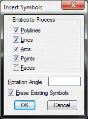
Select arcs, circles, faces, points, text,
lines and polylines.
Select objects: pick the sewer
polyline
The symbols are inserted at the three polyline endpoints.
21 You can reduce clutter by selecting the Freeze Layer by Selection command under the View menu, and picking a point number. The points freeze, leaving only linework and symbols. To bring the points back, use the Thaw Layer command under the View menu. The Freeze Layer and Thaw Layer commands go together, just like the Isolate and Restore Layers commands.
22 Next, you will create (in reduced size) your building dimensions. You can set the building dimension text size for the current work session using the Survey Text Defaults option of the Survey Text command on the Annotate menu. This dialog box appears:
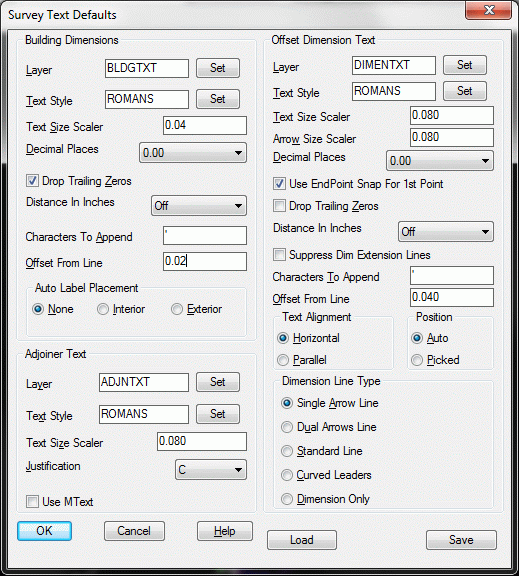
The changes you will make are in the upper-left section "Building Dimensions." Change the Text Size Scaler to 0.04, select Drop Trailing Zeros and change Offset From Line to 0.02.
The Drop Trailing Zeros option will label 17.0' as 17'. To save more space, you could blank the Characters to Append box, but not this time. Enter the name of a new layer for the building text called BTXT, so that building dimensions can be frozen to reduce the clutter even more. It is generally a good strategy to use layers for selective freezing and thawing.
Click OK on the above dialog box . On the Annotate menu, choose the Survey Text > Building Dimensions command. Click on the middle of the bottom segment of the building and then drag the alignment to the right, along the same bottom segment being dimensioned. The resulting label is shown below.
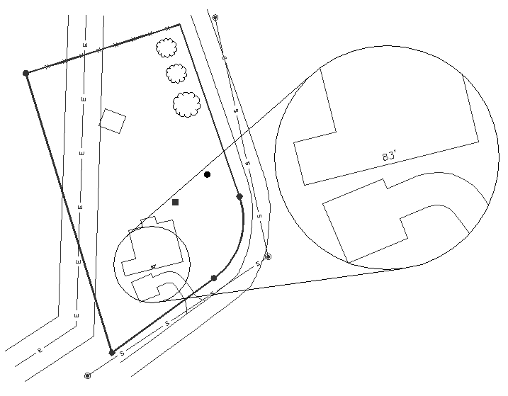
If you had dragged the cursor to the left rather than to the right, with the same near-parallel angle to the line, the 83' would be drawn below the building rather than above.
Another example is shown below. Select Annotate > Survey Text > Building Dimensions, and click on the left-most segment of the building. Then click roughly perpendicular to the left. This creates a perpendicular, rather than parallel, label as shown below.
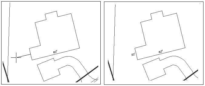
Label the rest of the building. Notice that the sides of the building that you are dimensioning are measured in even feet. Because you had selected the Drop Trailing Zeros option when you set your Survey Text Defaults, and you set the Decimal Places default at 0.0, the ".0" is not reflected in the labels:
If you choose the wrong direction while you are labeling, you can exit the command, or you can erase the incorrect dimension by typing E for erase at the command line, or you can enter U for undo to back out your last work. Once the labels are in place, you can type M for the Move command, and move the text to the desired position.
23 Next, you will label the offset dimension from property lines to two building corners, the SE corner as offset from the south property line, and the SW corner as offset from the west property line. Because of the options you set in the Survey Text Defaults dialog box above, Offset Dimensions will be created on layer DIMENTXT, and they will be horizontal, with arrowheads.
On the Annotate menu select Survey Text > Survey Text Defaults. The dialog previously shown will reappear. Change the Text Size and Arrow Size Scalers to 0.040. Then select Dual Arrows Line and click OK. On the Annotate menu, select the Survey Text > Offset Dimensions command.
[end on] Pick Bldg/Object Corner:
pick on the SE building corner
[perp] Pick Line To Offset From:
pick on the South property line
(before the arc, near the end of the driveway)
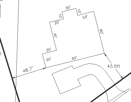
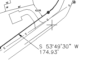
The setback is labeled 43.5'. Note the distance suffix is/was labeled as an apostrophe "'" rather than ft. If you desire an alternate label, re-examine the Characters to Append control of the Survey Text Defaults command.
On the Annotate menu, select Survey Text > Survey Text Defaults. Under Offset Dimension Text change the Text Alignment to Parallel instead of Horizontal. Click OK. Select Annotate > Survey Text > Offset Dimensions.
[end on] Pick Bldg/Object Corner:
pick on the SW building corner
[perp] Pick Line To Offset From:
pick on the West property line (avoid
the electric right-of-way line)
Use the Move command to move the 20' text label to the right, so that it is not overwritten by the offset dimension. The result is shown below:
Notice the display, within the above prompts, of the [end on] and [perp] snaps. When Carlson sets a snap for temporary use, it displays the snap within the brackets as shown. A building corner is always an endpoint, so the end snap always applies to the first pick. The offset is the perpendicular distance to the property lines, so the [perp] snap always applies to the second pick. The "per" (perpendicular) snap applies to offsets from arcs as well. In the case of arcs, the "per" snap finds the shortest, radial distance to the arc.
When you enter a snap at the keyboard in response to a "Pick object" request, type only the first 3 letters of the snap, such as "per" or "end". You could use the Offset Dimension command to label the Electric utility right-of-way distance of 50' total by entering "nea" (for nearest snap) for the first pick, then entering the default "per" snap for the second pick on the other side of the right-of-way.
24 Next, you will add adjoiner ownership text to the property lines. Select the Survey Text Defaults command, under the Annotate menu, and set the Adjoiner Text Justification option to C for centered, and the Text Size Scaler to 0.06. Click OK and then select the Adjoiner Text command on the Annotate > Survey Text menu.
Pick Line Or Polyline: pick the west property line
Pick Starting Point: pick a centering point west of the property for the
adjoiner text
Text: Brian W.
and Mary T. Jones
Text: D.B. 101,
P. 37
Text: press Enter
twice
This produces parallel, center-justified text on the west side of the property. Repeat the command for the north side. Press Enter to repeat the Adjoiner Text command or select it from the menus.
Pick Line Or Polyline: pick the north property line
Pick Starting Point: pick a centering point north of the north property
line
Text: Stan W.
Bosworth
Text: D.B. 94, P.
272
Text: press Enter
twice
The results are shown here:
25 Next, you will add bearing annotation. Select the Annotate menu, choose Angle/Distance, select the BearingDistance_ option to place Bearing and Distance above the line.
Define bearing or set text size
[Size/Points/<select line or polyline>]: pick the northern property line to the east, or right
side
The bearing direction will be labeled towards the picked end, which
is northeast.
Define bearing or set text size
[Size/Points/<select line or polyline>]: pick the eastern property line closest to the southern
endpoint of the line
To label the western property line on the lower (western) side of the line, select the _BearingDistance command on the Angle/Distance menu.
Define bearing or set text size [Size/Points/<select line or polyline>]: pick the western property line on the northern portion of the line
To label the southern line segment with a leader, on the Annotate menu select the Annotate with Leader > Brg-Dist with Leader command.
Size/Points/<Select line or
polyline>: pick the southern
property line segment on the southwest side
Pick end point for leader: pick a point for the
label position
Size/Points/<Select line or polyline>
(Enter to end): press Enter to
end
26 Next, you will want to annotate the arc in the drawing. The label will consist of four entries: arc length, radius, chord bearing (direction) and chord distance.
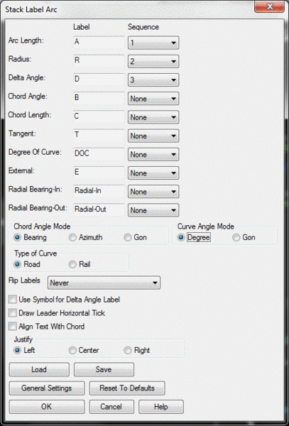
From the Annotate menu, select the Annotate Arc > Stack Label Arc command.
Options/Points/<Select
arc>]: O
At the Command prompt, type O for Options and the Stack Label Arc
dialog box appears.
Options/Points/<Select arc>]:
pick the arc
Pick point for labels: pick a point to the right to place the label
As the cursor moves, the text "ghosts", allowing you to make the
best possible placement decision
Pick point to start leader at ([Enter] for
none): pick a point on or near the arc
for the arrowhead
To point: pick a
point near the labels
Options/Points/<Select arc>] (Enter to
end): press Enter to end
If your arcs/curves appear as "chorded" segments, type REGEN at the command prompt to "regenerate" the arc. Even if an arc shows up on the screen as a group of jagged chords, it will plot as a smooth arc to a printer or plotter.
27 Next, you will label the trees, the shed, and the building using a special leader, for a hand-drafted appearance. Under the Draw menu, select the Leader > Special Leader command.
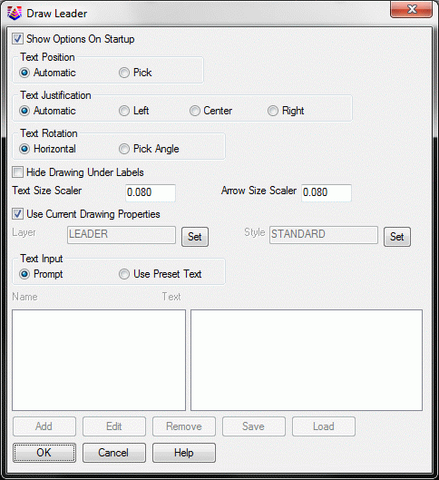
Click OK
Options/Size/Pick Arrow Location:
pick near the southern most corner of the
shed
Text location: pick slightly down and to the right
Text: Shed
Text: press Enter
twice to end
Repeat the process for all the special leader text items shown in the drawing below. In the case of the 18" Oak trees, create just one leader with text and on the second oak tree, create only the leader and then press Enter when asked for Text. For the best appearance, enter 18"Oak and 24"Oak with no spaces between the characters.
Your drawing should be similar to this one:
28 You can add a North Arrow and Bar Scale by selecting these options under the Annotate menu. When you place the North Arrow, pick your North Arrow symbol, maybe change the scale, and click OK. Then pick an insertion point. You place the Bar Scale by answering the prompts and picking a location. Both the North Arrow and the Bar Scale can be moved to desired locations with the Move command on the Edit menu.
29 Next, you will insert a title block with a border. Select the Title Block command from the Settings menu.
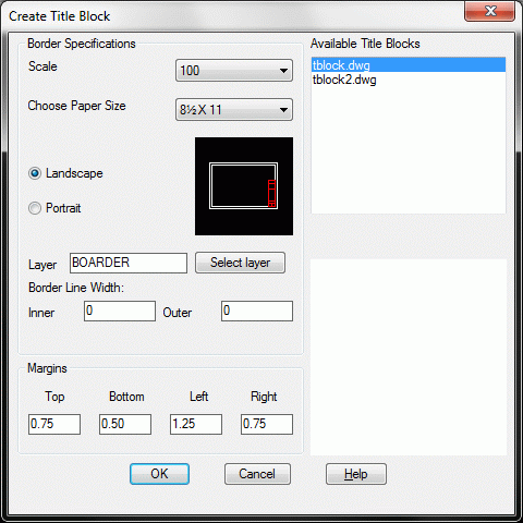
Choose paper size A1 (portrait view, 8-1/2 by 11). Click OK. Pick a point below and to the left of the survey in order to locate the lower-left corner of the border outer line. Remember that the title block will be at the bottom, so leave extra room at the bottom.
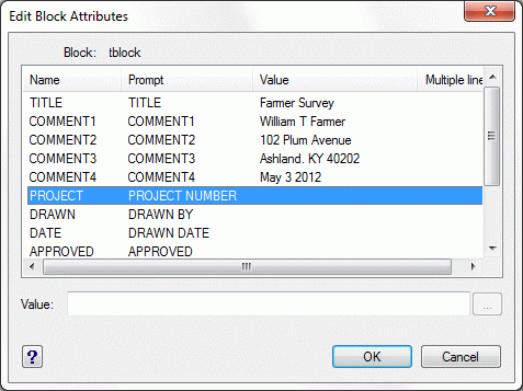
The following dialog appears, prompting you for the attributes of the title block. Be sure to also click Next in order to enter in more attributes.
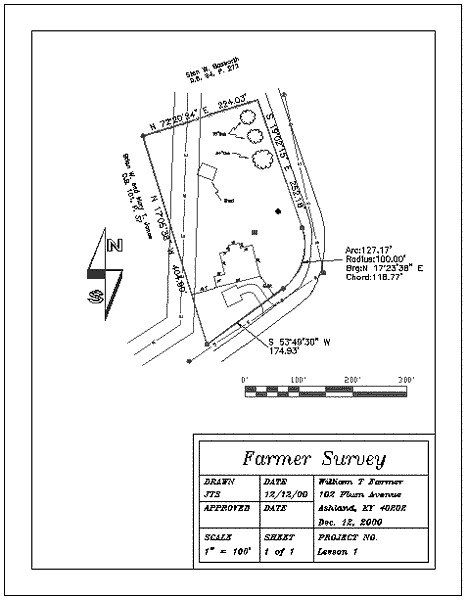
Your drawing should resemble the one shown below.
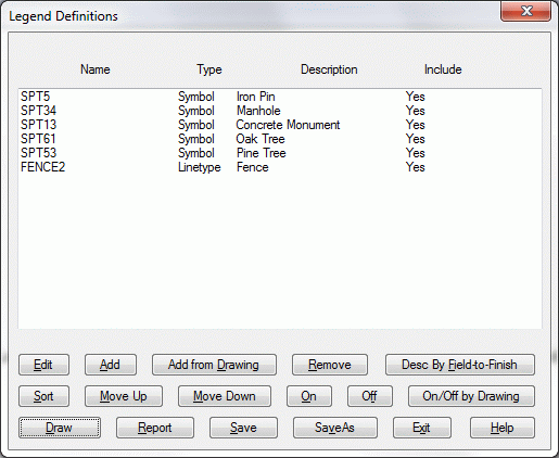
30 Next, you will add a legend. On the Annotate menu, select the Draw Legend command. Choose the New tab, and then Open the default legend name. When the dialog box appears, select Add from Drawing. You will make one pick for each symbol you want to appear in the legend. Select one of the sewer manholes, one of the iron pins, the concrete monument, one oak tree and the pine tree. Press enter. You will then see the symbols that you picked listed.
If you want to change the order of the items in the list, use the Move Up and Move Down buttons, after first selecting and highlighting the item to be moved. After the list is ordered correctly, highlight one item on the list and click the Edit button to edit the symbol definition.
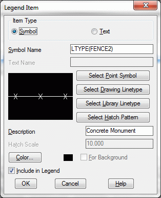
Edit each symbol definition individually and type the following descriptions in the description box:
SPT5 = "Iron Pin"Below is the symbol definition, with Description, for SPT13.
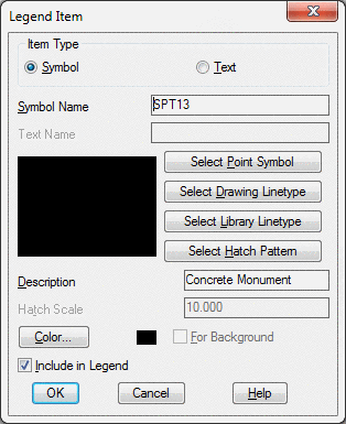
Select the Draw option from the Legend Definitions dialog box. Set the defaults as shown below.
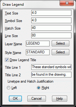
Click OK. Pick a point for the legend at a coordinate location approximately at 5260,4380. Then click Exit.
You may need to move the fence line portion of the legend to fit in the tight space. You also may need to move the previously drawn bar scale. Use the Move command to do this. The following shows the drawing to this point:
If you wish to reset the spacing of the sewer and electric utility annotation, use the LTSCALE box in the Drawing Setup dialog box found under the Settings menu. (The setting is 50 in this example).
31 Next, you will use Dtext to label the road and Mtext to create a certification block. Zoom in on the area shown below. At the command line, type Dtext.
Specify start point of text or
[Justify/Style]: R (for
right-justified)
Specify right endpoint of text
baseline: pick a point as shown
below, just to the left of the leader annotation
Specify height <8.00>:
10
Specify rotation angle of text
<E>: pick a point as
shown below by the location of the crosshair
Text: Meadow
Lane
Text: press
Enter
This right-justifies the label Meadow Lane, ending it before it contacts the leader line.
Now you will enter a certification using Mtext. The Mtext command stretches an entire block of text. This command breaks up the lines in the block of text depending on how you edit and adjust the Mtext window. First, use the View > Extents command to view the entire drawing. Then type Mtext at the command line.
Specify first corner: pick a point in the 5660,4980 range
Specify opposite corner or
[Height/Justify/Line spacing/Rotation/Style/Width]:
pick a point below and to the right of
the first, but inside the inside border line
You now see a dialog box that displays all the text heights that you have used in the drawing. Choose the text height of 8. Then type the following into the dialog box:
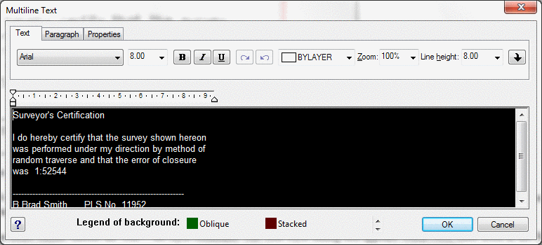
The command "wraps" the text when it runs out of space in the Mtext window. Click OK at the upper right to place this text into the drawing.
After the Mtext is plotted, you can click on the text to activate the grips. All 4 corners highlight as grips. When you pick on a grip, you can expand or change the shape of the Mtext rectangle. When you do this the text adjusts automatically, wrapping into more or fewer lines of text based on the size of the MText window. You can also move the entire text block to a new location.
32 Next, you
will define a text style and then add text using that style. On the
Draw Menu, choose the Text > Set Style command. The Text Style
dialog box appears.
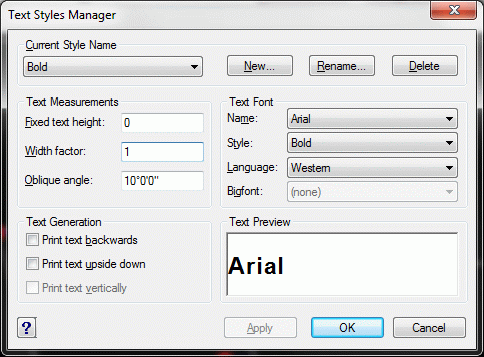
Click New, enter Bold in the New Text Style dialog, and click
OK.
Create a Bold Style consisting of the Arial Black font tilted at a 10° oblique angle, by entering the settings as show below.
Then click Apply and Close. Now, run the Dtext command by typing Dtext at the command line, and place the text at the top of the drawing as follows:
Specify start point of text or
[Justify/Style]: pick a point near the
northwest corner of the drawing
Specify height <10.00>:
20
Specify rotation angle of text <N 54d40'16"
E>: E for due East
Text: William T. Farmer
Text: press Enter
twice
33 Next, you will create an area label for the drawing. Select the Area Defaults command, under the Area/Layout menu, and change the Precision for the Acres labels to 2 decimal places.
Select the Area by Lines & Arcs command, under the Area/Layout menu. When prompted to Select objects, pick the 2 polylines that taken together, completely enclose the property.
Pick an area labeling centering point for the area label under the William T. Farmer title at the top of the drawing.
34 Next, bring the points back and draw a contour map. To draw the points, use the Thaw Layer command under the View menu. If you did not complete this lesson in one sitting, then Carlson won't "remember" what layer to thaw. In that case, select the Layer Control command on the View menu, and thaw the PNTS layer by turning the snowflake to a sun symbol.
Go to the Surface menu and select the Triangulate & Contour command. On the Contour tab.
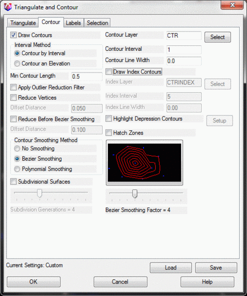
In this Contour tab section, change the contour interval to 1.0. Now click on the Triangulate tab, and then click on Use Inclusion/Exclusion Areas. Press OK and then answer as follows:
Select the Inclusion perimeter polylines or
ENTER for none.
Select objects: press
Enter
We have no "inclusion" perimeter.
Select the Exclusion perimeter polylines or
ENTER for none.
Select objects: select the building
and the shed, and then press Enter
Since the building and shed are closed polygons acting as exclusion
perimeters, the contours will not pass through them when they are
created.
Select the points and breaklines to
Triangulate.
Select objects: type ALL and then
press Enter twice
The contour map is created. Freeze the points again by using View > Freeze Layer and picking one of the points.
35 Next, label the contours. From the Surface menu, select the Contour Utilities > Contour Elevation Label. Select OK after matching the settings in the dialog box shown here:
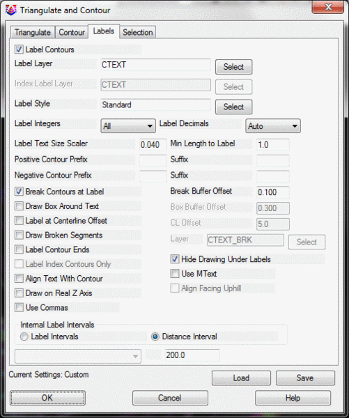
Now pick two points that cross through one or more contours. The contours are automatically labeled using the current text style. You can use the Change Text Font command, part of the Text command in the Edit menu, to change the font to Romans, or to another font, if you wish to.
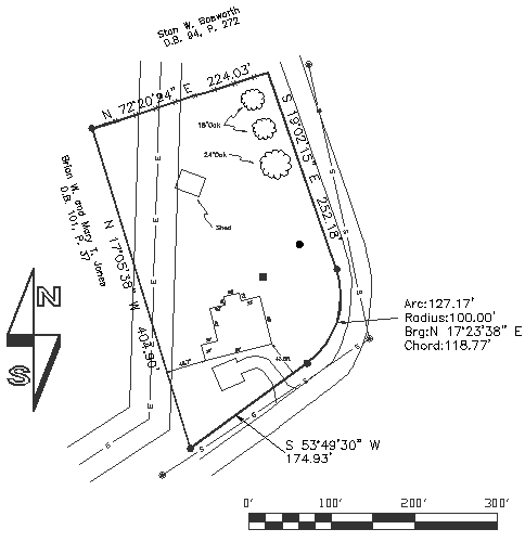
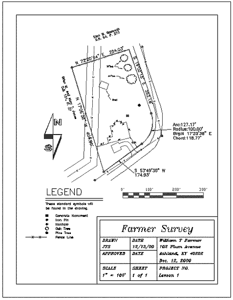
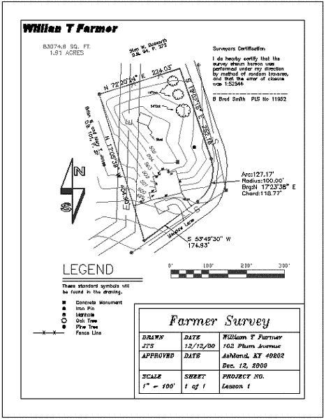
The Completed Plat is shown here:
If you have not saved your drawing for awhile, now is a good time to do it. Use the Save command on the File menu.
This completes the Lesson 2 tutorial: Making a Plat.