This command displays a dialog for the current Lot Network Settings which specifies the lot network name, road network name, label settings, setback settings, hatch settings, building placement settings, lot type settings and lot area tolerance.
 Lot
Network: Click Select for the
Lot Network name and choose the Lot Network file (.ltn).
Lot
Network: Click Select for the
Lot Network name and choose the Lot Network file (.ltn).
Road Network: Click Select for the Road Network name and choose the Road Network file (.rdn).
Starting Lot Name: Indicate the starting Lot Name. As Lots are created, the trailing digit will be incremented by a value of 1.
Lot Area Tolerance: When creating lots to a target area, the program will finish adjustments when the area is within this tolerance of the target.
Edge Direction: Select an option to have new Lot lines drawn either Away From Frontage or Toward Frontage.
Output Lot File: This option automatically outputs a Lot file (.lot) from the Lot Network. When this option is enabled, set the Lot and Coordinate files to create. There is also an option to draw the lot file points. The settings from Points > Point Defaults are used for drawing these points.
Automatic Label Updates: Enable this option if Lot labels should automatically update themselves if a Lot is altered or adjusted.
Default Lot Type: Settings in this section of the dialog box will be applied to all new Lots created using the "Default" Lot type.Lot Line Layer: Specify a new layer or click Select to choose an existing layer for newly created Lot lines
Label Lines and Arcs: Enable this option if you want this routine to label the newly created lines and arcs at the time new Lots are generated. For Line/Curve Label Settings, you can click Select to specify the Auto Annotate settings file (.aan) or click Edit to make changes to the Auto Annotate settings. For General Label Settings, you can click Select to specify the Annotation General Settings file (.adf) or click Edit to make changes to the Annotate Defaults settings.
Label Areas: Enable this option if you want this routine to label the areas at the time new Lots are generated. For Area Label Settings, you can click Select to specify the Area Defaults file (.ars) or click Edit to make changes to the Area Defaults settings. For Area Table Settings, you can click Select to specify the Area Table Settings file (.atb) or click Edit to make changes to the Area Table Defaults settings.
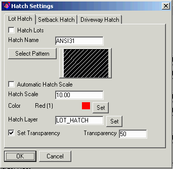
Draw Hatch: Enable this option if you want this routine to draw a Hatch pattern inside Lots at the time new Lots are generated. Click Settings to adjust the Hatch Settings as desired. In addition to hatching the lot area, you can also hatch the setback and driveway areas. Each area has separate hatch property settings.
 Building Placement
Settings: Click the Building
Placement Settings button to specify the values that should be
followed when building pads are placed using the Lot Network
routines.
Building Placement
Settings: Click the Building
Placement Settings button to specify the values that should be
followed when building pads are placed using the Lot Network
routines. 
Front Setback: Sets the amount of setback for lot segments that are along the frontage.
Side Setback: Sets the amount of setback for lot segments that are partially along the frontage.
Back Setback: Sets the amount of setback for lot segments that are not along the frontage.
Draw Setbacks: Enable this option if you want this routine to draw Setback lines at the time new Lots are generated.Buildable Polyline
Layer: The Lot Network Report
looks for closed polylines on this layer within the lots for
reporting the buildable width and depth. This buildable area is a
separate reporting option from the setback.
Building Polyline
Layer: Specify the layer on
which building pad polylines should be drawn or click the Select
button to choose an existing layer.
Rotate Building By: This setting controls whether to align the building pads to be perpendicular with the frontage or to be parallel with the lot edges.
Draw Building Symbols: Enable this option to draw building symbols (blocks).
Building Symbol Layer: Specify the layer on which building pad symbols should be placed or click the Select button to choose an existing layer.
Symbol: Click the Select button to specify the name of the building symbol.
Building Pad Width: Specify the width of the building pad polyline.
Building Pad Depth: Specify the depth of the building pad polyline.
Building Pad
Setback: Specify the distance
behind the Setback line at which to place building pad polylines.
Enter "0" to have building pad polylines placed directly on the
Setback.
Draw Driveways: Creates driveways as closed polylines between the building pad and lot frontage.
Driveway Polyline Layer: Sets the layer for the driveway polylines to create.
Driveway Left Offset: Facing the building pad from the front, this setting positions the left side of the driveway on the building pad.
Driveway Right Offset: Facing the building pad from the front, this setting positions the right side of the driveway on the building pad.
Driveway Setback: Sets the offset of the driveway from the building pad.
Driveway Curb Radius: Sets the curb return radius for where the driveway connects to the frontage.
Additional Building Pads: Click the Add button to create additional building pads, the Edit button to modify existing building pads and the Remove button to delete building pads.

LotNet sample showing setbacks and examples of varying building sizes.

LotNet sample showing 3D building symbol.
Additional Lot Types: Settings established in this section of the dialog box allow you to create additional types of Lots in order to apply different Line/Curve, Area, Area Table, Setback, Hatch and Building Placement Settings according to their specified Lot Type. Additionally, running a Lot Network Report will break out Lot data based on Lot Type and Lot Network Inspector will display Lot Type.
Add, Edit and Remove: Use these buttons to create additional Lot types, edit or remove existing Lot types.

Pulldown Menu Location: Area/Layout
Keyboard Command: lotnet_config
Prerequisite: None