Auto Annotate
This command allows you to select a group of lines, arcs and/or
polylines to be labeled. It allows for any combination of line and
distance labeling, and also any combination of arc
labeling.
You can position the features of the labels, once in the
Auto-Annotate dialog, by using the Row, Side, Order, Orientation
and Position Types options, all found under Lines tab. For Arcs,
you can select the Arcs tab and determine the type of
auto-annotating you would prefer for arc entities. As you select
different options, you can see the changes in the preview display
of the entry dialog. You will select the Angle Format in terms of
Bearing, Azimuths and Gons and there is an important feature that
allows you to avoid label overlaps. This is done by applying
specific, user-defined settings. When labeling arcs, there are
options to set the label prefixes for curve annotation. The
Settings button will bring you to the Annotation Defaults dialog,
as explained in a previous section. Defaults will restore the prior
settings.
Apply Label Settings by Layer brings up another dialog box which
allows you to import from file, or load, predetermined
configurations. There is an option to have different label settings
applied by layer. Apply Label Settings By Layer allows you to set,
load, and save your preferred variables.
The Avoid Label Overlap option can bring up a special dialog
called the Overlap Manager. This screen, which contains extra tools
for, as an example, sliding or stacking the labels that are
overlapping and conflicting with drawing entities, gives you the
real-time ability to move along the plan and make your corrections.
This also will help you to avoid overlapping with other labels,
text, symbols and linework -- including fence and utility
lines. In this Overlap Manager, docked on the left side of the
screen. it is recommended that you use the Back and Next button
frequently in order to review, adjust and correct your
drawing.
Auto-Annotate dialog
starts with the Lines
(tab).
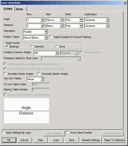 Angle/Distance: Allows you to
enter the what row the Angle label is on, what side and the order
of the label on the linework. The same applies for Distance labels.
Notice the preview display changing.
Angle/Distance: Allows you to
enter the what row the Angle label is on, what side and the order
of the label on the linework. The same applies for Distance labels.
Notice the preview display changing.
Row: Using numbers (1 or
2), or choosing None, you can determine the order and appearance of
the descriptions. Note the change in the preview display.
Side: Choose inside or
outside of the line.
Order: If you determine
that the annotations are to be on the same row and same side of the
line, then you must pick the order in which they will appear, from
left to right.
Justification: This option
gives the ability to left or right justify labels at ends of line
or center justify the labels.
Orientation: This
offers this choice between parallel or perpendicular with regards
to the labels' orientation to the line being labeled.
Position Types: Determined
how each label is placed in relationship to the line and the other
label. The Inside/Outside For Closed Polylines treats the
first position type as the inside position and the second as
outside for labeling closed polylines which applies when labeling
lot polylines that are closed and you want a style like distances
on the inside of the lots and bearings on the outside.
Angle Format: Bearing,
azimuths or gons are the choices.
Combine Common
Angles: This allows the user to reduce label clutter
by minimizing labeling of serial and parallel linework. Choices are
Off, Series, Parallel and "Series and Parallel". Series common
angles are those where serially connected linework share the same
angle. Common series angles are labeled at the mid-point of the
series of connected line segments. When series common angles are
selected they may be drawn stacked on the same side as the distance
labels or on the opposite side from the distance labels. Also, for
serial common angles the total distance may be included in the
label. Parallel common angles are those where adjacent areas share
parallel lines that include the line that bisects the areas. In
this case, only the outer-most lines of the set of parallel lines
will be labeled with the angle.
The common angle
labels have separate settings for layer, style, size and offset.
Please see the section "Annotate Defaults" for information on how
to control these settings.
The following example shows the results of
combining common serial labels, including totaling of the
distances:
The following example shows the results of
combining common serial and parallel labels:
Compress Labels
for Short Lines: When angle and distance labels are
being placed on the same side and row, this feature allows the user
to place the label on different rows in the case that the label
will not fit on the line otherwise. The options are Off, "Angle
Above, Distance Below", "Distance Above, Angle Below", "Stacked
Angle-Distance" and "Stacked Distance-Angle".
Add Space Between Angle and
Distance Labels: When angle and distance labels are being
placed on the same side and row, this feature allows the user to
have the angle and distance labels spread apart from each other as
allowed by the length of the line being annotated.
Reduce Space Between Angle and Distance Labels: When angle
and distance labels are on the same row, this option puts a single
space between them. Otherwise, there are two spaces.
Create Separate Angle and Distance Labels: When the angle
and distance labels are on the same row, this option creates them
as separate text entities. Otherwise, the labels are combined in a
single text entity as long as their text styles match from
Annotation Defaults.
Flip Text for Twist Screen: This option automatically flips
the labels when needed to make them right-side up.
Use Line Tables: Line tables are sometimes preferred
as they keep the drawing linework clean and free of labeling.
Choices are Always, Never or By Scaler. If By Scalar is chosen "To
Line Table Scaler" is enabled.
To Line Table Scaler:
If the length of the line is less than this minimum, the line is
labeled as a line table entry. The To Line Table Scaler is relative
to the current horizontal scale and represents the length of the
line in plotted inches.
Starting Table Number: User
choice. You might change this because perhaps you have another
group of line labels, in table form, in the drawing. Line table
entries are numbered sequentially beginning at the line Starting
Table Number. The location for the line table can be picked if
there is no current table. Otherwise, Auto Annotate will add to the
end of the current line table. To set the location for the current
line table, run the Table Header command in the Annotate >
Line/Curve Table menu.
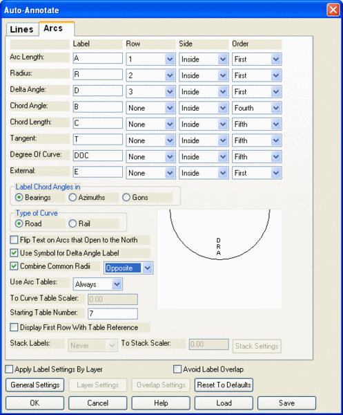
Auto-Annotate
dialog box, by selecting the Arcs tab, displays the options for
auto-annotating arcs. The columns are described, followed by the
rest of the options.
Label: Here
you might alter slightly the defaults by entering a letter or
acronym that will represent to type of calculation. Or you could
leave it alone.
Row: Using numbers, or
choosing None, you can determine the order of the descriptions, and
determine whether or not some might be left off altogether.
Side: Choose inside or
outside of the arc.
Order: If you determine
that the annotations are to be on the same row and same side of the
curve, then you must pick the order in which they will appear, from
left to right.
Label Chord Angles in:
Bearing, azimuths or gons are the choices.
Type of Curve: Choose
between Road and Rail.
Flip
Text on Arcs that Open to the North: Clicking here might
make for a easier to read finished plan. User preference.
Use Symbol for Delta Angle
Label: The popular and traditional triangle-shaped symbol
can be used, instead of the letter D, or any other letter(s).
Combine Common Radii: This
allows the user to reduce label clutter by minimizing labeling of
connected arc segments that share a common radius and center point.
When selected, only one radius label will be generated for such arc
segments. The following shows an example where a curve made of
three arc segments is labeled with only one radius label. The
radius label is placed offset to the mid-point of the combined
arcs.
Use Arc
Tables: Curve tables are sometimes preferred as they keep
the drawing linework clean and free of labeling. Choices are
Always, Never or By Scaler. If By Scalar is chosen "To Curve Table
Scaler" is enabled.
To Curve Table Scaler: The
To Curve Table Scaler applies when the Type of Arc label options is
not set to Curve Table. If the length of the arc is less than this
minimum, the arc is labeled as a curve table entry. The To Curve
Table Scaler is relative to the current horizontal scale and
represents the length of the arc in plotted inches.
Starting Table Number: The
Starting Table Number is the starting number for the first line
entered in the Curve Table. Curve Table entries are numbered
sequentially from the curve Starting Table Number. The location for
Curve Tables can be picked if there is no current table. Otherwise,
Auto Annotate will add to the end of the current Curve Table. To
set the location for the current Curve Table, run the Table Header
command in the Annotate > Line/Curve Table menu.
Stack Labels: Stacked
labels are sometimes preferred as they can help reduce label
overlapping. Choices are Always, Never or By Scaler. If By Scalar
is chosen "To Stack Scaler" is enabled.
To Stack Scaler: When
Stack Labels is set to "To Stack Scaler" this control is enabled.
If the length of the arc is less than this minimum, the arc is
labeled as a stacked label. The To Stack Scaler is relative to the
current horizontal scale and represents the length of the arc in
plotted inches. The Stack Settings button is enabled when Stack
Labels is set to Always or By Scaler. This button brings up the
Stack Arc Labels which displays the options for creating stacked
arcs labels. The columns are described, followed by the rest of the
options.
Label: Here you might alter
slightly the defaults by entering a letter or acronym that will
represent to type of calculation. Or you could leave it alone.
Row: Using numbers, or
choosing None, you can determine the order of the labels, and
determine whether or not some might be left off altogether.
Label Chord Angles in:
Bearing, azimuths or gons are the choices.
Side: Choose inside or
outside of the arc.
Type of Curve: Choose
between Road and Rail.
Flip
Text on Arcs that Open to the North: Clicking here might
make for a easier to read finished plan. User preference.
Use Symbol for Delta Angle
Label: The popular and traditional triangle-shaped symbol
can be used, instead of the letter D, or any other letter(s).
Draw Leader for Stacked
Labels: When checked, a leader will be drawn from the
stacked label to the mid-point of the arc.
Stack Label Offset: This
value multiplied by the horizontal scale defines the distance that
an annotation label is placed from its defining arc.
Align Text With Chord:
Determine whether the stacked label is oriented horizontally
(unchecked) or in the direction of the chord (checked).
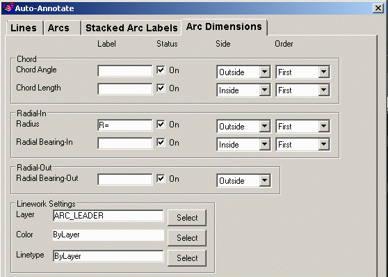
Arc Dimensions
The Arc Dimensions style draws and annotates lines for each arc for
the chord and radial lines. To use the Arc Dimensions label style,
turn on Use Arc Dimension Labeling on the Arcs tab. On the
Arc Dimensions tab, there are settings for the label prefix and
position for the chord angle, chord length, radius and radial
angles. You can also set the layer, color and linetype for the arc
dimension lines.
Auto-Annotate dialog commands, common to both Lines and
Arcs.
Apply Label Settings By
Layer: See the Label By Label Settings dialog and details
below.
Avoid Label Overlap: See
dialog and details below.
General Settings: Brings
you to the A ate Defaults dialog.
Layer Settings: Apply Label
Settings By Layer option must be clicked in order to activate. You
will then see the Label By Layer Settings dialog.
Overlap
Settings: Avoid Label Overlap option must be clicked in
order to activate. Brings up the Avoid Label Overlap dialog.
Reset to Defaults: This
returns you to the default label values.
Point Group: This function prompts for a point group to use
for the input data to annotate. The program uses the series of
points to define the lines and arcs to annotate.
Load: You can load an existing .AAN file.
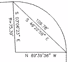
We will now say, for example, that with linework only to label
in the drawing we run this routine. We first decide to go without
the Avoid Label Overlap feature. This can be done by unclicking
this option in the Auto-Annotate dialog. We will say that there is
a fence line cutting through our property line, the property lines
being the lines that we want to auto-annotate. In going without
Auto Annotate's overlap protection, we perform Auto Annotate and we
see that there is an overlap, with the labels running into the
property lines and the fence line.
Panning and zooming the screen shows the problems we confront.
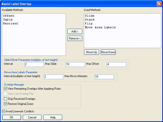
Now, run Auto annotate again, but this time click ON the Avoid
Label Overlap feature. Then click Overlap Settings button which
brings up a dialog as shown below. This program and this specific
dialog box has many different methods for fixing the overlaps. We
will choose the different methods to apply.
First, we will choose Slide. This slides the labels along the
linework. We can even choose a maximum amount of slide and other
related parameters. We will also turn on the Stack method. The
Avoid Linework Conflicts feature pertains to that fence line we
have. Finally, click OK. Now can pick the linework. Note that you
do not need to erase the existing auto annotate labels ahead of
time. This command will remember that those labels were created
with this command. It will simply replace the entire group of
labels with the new auto annotate labels.
The result, with overlap detection on, is that this routine
fixed 7 out of 7 of the conflicts. It slid some of the labels over
and stacked others. You can also run Auto Annotate Overlap with
manual mode. To do this, remove the automatic options (such
as Stack, Slide, etc.) and click View Remaining Overlaps After
Applying Rules ON. Say OK. It docks the Overlap Manager on the left
side of the screen.
You can then fix the conflicts with this Overlap Manager by
using the different methods presented in this new window. This
manager will highlights the conflicts, it will, for example, slide
to the next conflict and allow you to pick a new position. Hit the
Next several times. Again, stack one, slide another over, and
perform other changes. Then choose Close.
Also, remember that depending on the linework layer, you can
even have different annotation styles. There is also an option to
have different label settings "by layer". These decisions are made
by using the Label By Layer Settings dialog options. To get to this
dialog, click on the Layer Settings button at the bottom of the
Auto-Annotate dialog.
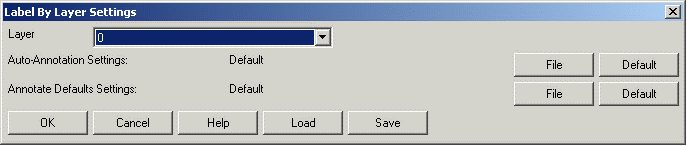
Label By Layer Settings option and
dialog.
Layer: Select a layer
from the existing list of layers. If the linework you select and to
be labeled is on this layer, the parameters that you set in this
dialog will be reflected in all labels.
Auto-Annotation Settings:
Select an existing Annotation Settings file (AAN) by clicking the
File button on the right.
Or stick with the defaults.
Auto-Defaults Settings:
Select an existing Default Settings File (ADF) by clicking the
File button on the right.
Or stick with the defaults.
Load: Select this option in
order to load an existing layer file (LAY) to load.
Avoid Label Overlap option and
dialog.
|
|
|
Overlap Settings dialog
|
Available Methods: Your
choices. Pick from these.
Used Methods: Different
ways in which this routine attempts to resolve the label overlaps.
The overlap resolution attempt methods are applied in the order
listed here.
Slide: If this is
selected then the labels will be moved parallel to your linework
until they do not overlap. The labels will not move past the end of
the linework or the Max Slide which you determine.
Offset: will move your
labels perpendicular to your linework as far as you set the Max
Offset.
Table: Replaces your labels
with a numbers and create a table of the numbers with the
corresponding labels.
Reorient: If chosen, the
labels will change orientation in the plain view to avoid
overlapping.
Flip: It will flip your label onto the other side of the
linework.
Stack: It will stack or unstack the text of your labels to
avoid overlapping.
Move Area Labels: This
method, which only applies to area labels, will attempt to move the
area label to the closest place within the area that doesn't
overlap with any other labels. You can control the move interval
(distance between move attempts) and total number of move attempts
by setting the values "Interval
(multiples of text height)" and "Max Move Attempts" in the "Move Area Labels Parameter"
section:
You can use any combination of these
commands by using the add/remove button. You can also determine the
order in which the command tries a method by using the Move Up and Move Down buttons. If a solution is not
found by using the first method then the next method is used in
descending order.
Add/Remove: Some methods you might prefer not to
use.
Slide/Offset Parameter (multiples of text
height): These are variable that help you to slide or offset
the label(s) in question.
View Remaining Overlaps After
Applying Rules: This option will help you to see what still
needs treatment.
View Last Overlap File: When it is checked, the
Overlap Manager will return to the previous labels that were under
review.
Skip Resolved Overlaps: When it is unchecked, the Overlap
Manager will display all the labels that were moved by the command
as a final check to you.
Restore Original Zoom: This will restore the zoom you were
previously at before running the command.
Avoid Linework Conflicts:
This is an extra precaution for when linework conflicts
exist.
If there is a conflict, the following
Overlap Manager dialog appears on the screen. It zooms to the
conflict and provides you with the necessary tools to resolve the
issues that need to be addressed. Many of the choices selected in
the earlier dialog boxes can be modified yet again in the Overlap
Manager, in your quest for a clean looking drawing. Within this
special window you can zoom, pan, move to the next conflict, and
perform many other tasks.
The Overlap Manager screen
appears as a docked dialog window to the left of the main
screen.
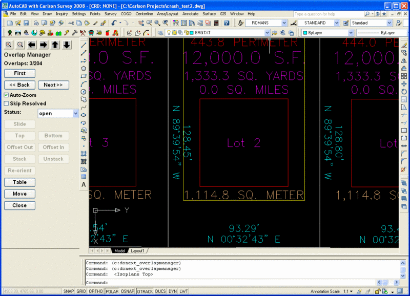
The Overlap Manager can be used to
manually check and change label overlaps. The current overlap item
will be have a yellow box drawn around it to help make it clear
which item is the one currently being worked on. If you check on
"View Remaining Overlaps After Applying Rules" then any remaining
overlaps will be zoomed in on and you will have the ability with
the Overlap Manager to flip through and fix or ignore the
unresolved labels. When the current overlap item is an area label,
only the Move and Table button will be enabled as these are the
only two manual methods that can be applied to these types of
labels. For line and curve labels, all methods will be
enabled.
Prompts
Auto Annotate Dialog Choose settings and click OK.
Select Lines, Arcs, and/or Polylines to Annotate.
Select Objects: pick entities. Select the group of
lines, arcs and/or polylines you want to annotate.
Pulldown Menu Location:
Annotate
Keyboard Command: autoann
Prerequisite: Lines, arcs or polylines to annotate