
The Create Sewer Structure or Edit Sewer Structure command is a very powerful program for the design and analysis of networks. A storm sewer network is generally made up of pipes, structures and inlets. A sanitary/utility network, unlike a storm sewer, doesn't have inlets. There may be more than one pipe entering a structure, but only one can exit. The network type is specified via the Sewer Network Settings command. Depending on the type of sewer network being created or edited, you'll either have the full-featured editing control (described below) for Storm Sewer networks or a more stream-lined Create/Edit Sanitary/Utility Structure command.
This command allows you to construct a graphical representation of a pipe network in the active drawing with associated data including (but not limited to) pipe, structure, inlet, watershed and rainfall details. The Edit/Create Sewer Structure command takes the form of a "docked dialog box" as illustrated below. This flexible interface allows direct access to the Command, graphic window, pull-down menus and toolbar... all while the docked dialog box is open.
The storm sewer network is solved using the standard step gradually varied flow methods. This is an iterative procedure used to determine the energy and hydraulic terms at the end of each pipe. The direction of computation is from the most downstream pipe of the network to the most upstream pipe. The following steady state energy equation is used between the upstream and downstream ends of every pipe. Please refer to HEC-22 manual for details. You can design the sewer system with one rainfall return period, and analyze it with another return period.
Zu + Vu2 / 2g = Zd + Vd2 / 2g + Hf
where: Zu = upstream water surface elevation
Vu2 / 2g = upstream velocity head
Zd = downstream water surface elevation
Vd2/ 2g = downstream velocity head
Hf = friction loss
The Manning's equation is applied to determine the friction slope.
Q = (M/n) A R2/3 Sf1/2
where: Q = discharge
M = 1.49 for
English unit, 1.0 for Metric units
n =
Manning's roughness coefficient
A =
cross-sectional area
R =
hydraulic radius
Sf = friction slope
Then the friction loss along the pipe is computed by the following equation:
Hf = SfL
where: L = pipe length
With the friction loss calculated, the elevation of the upstream water surface can be determined.
First set up the working environment by running command Sewer Network Settings under Network → Sewer Network Setup menu. Then select Edit/Create Sewer Structure. If you are creating a sewer structure, pick a location in the plan view where you want to locate the structure, otherwise click on an existing structure symbol. After a structure has been located, the dock dialog displays, and the current structure symbol is highlighted in the drawing. Following is an example of the dock dialog.

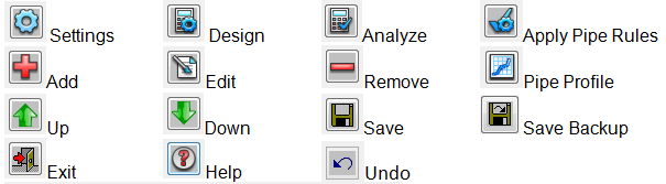
Settings: This function performs as same as the Sewer Network Settings command except for the settings found on the General tab.
Design: When you select any Automation settings in the Sewer Network Settings, i.e. Auto Set All Sewer Pipe Sizes, Auto Set All the Invert Elevation of the Sewer Network and etc., this function would design the profile of sewer lines, such as pipe inverts and sizes, depending on the design settings, and then performs the hydraulic calculation. If you don't choose any Automation settings, this button would work just as the Analyze button.
When designing pipe sizes, the program first estimates the design flow for each pipe in the system and makes an initial selection of the size, from the pipe size library, required for each pipe.
Typically, pipe slope is set to the actual invert slope. If the pipe invert elevations are to be designed, pipe slope is assumed as the same as the normal slope. The Manning's equation is then used to solve the required pipe size given the pipe Manning's n coefficient, design discharge and slope. The calculated size is then rounded up to an available size in the pipe size library. When designing pipe invert elevations, the criterion of minimizing ground cover at all locations along pipe lines is used.
After initial design, the program analyzes gradually varied flow with the standard step method for a few iterations. It uses the actual velocity from the previous calculation to determine the total time of concentration, and therefore the actual flow and hydraulic grade line, modifies the pipe sizes and invert elevations based on the design constraints, and then performs next iteration of computation, until the result is stable and meets the design constraints. Any violations of the design settings will be shown in a warning message dialog window.
Analyze: This function conducts the hydraulic calculation on the existing sewer network.
The program analyzes gradually varied flow with the standard step method and reports the results such as hydraulic grade line, energy grade line, flow velocity, drainage flow rate and inlet interception, etc. Any violations of the design settings will be shown in a warning message dialog window.
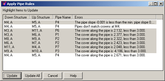
Apply Pipe Rules: Click this button to correct detected pipe problems against those specified in the Pipe Size Library. Use standard Windows click, shift+click and/or ctrl+click functionality to select multiple pipes at the same time.
Add: This function allows you to create a new structure. The new structure will connect to the nearest structure found in the network if you select the Auto Connect Structures option.
Edit: This function allows you to pick an existing structure symbol in the plan view to make the structure active for editing.
Remove: This function removes the structure that you pick and also removes the corresponding pipes and then reconstructs the network.
Up: Moves to the upstream structure and makes it active.
Down: Moves to the downstream structure and makes it active.
Save: Prompts to save any pending network
changes.
Save Backup: Prompts to save the network data in a backup
file.
Undo: Can undo the changes made to
the sewer network. One click reverts one change.
Exit: Dismisses the docked dialog
box.
Just below the icons are four tabs. The tabs and each function are described below tabs:
Structure Name: Provide a unique value to identify the structure in the network.
System Name: A name for current network. All the structures within a sewer line must have the same System Name (there can be more than one sewer line in a sewer (.SEW) file.
Description: Provide an optional note that further describes the structure.
Inlet: Select a pre-defined inlet to be associated with the structure or click the Library button to select an Inlet or make changes to the Inlet Library. In addition to associating an Inlet with the Structure, the Library button also populates the Symbol Name control with the default value stored in the Inlet Library.
Structure ID: Select a pre-defined structure or click the
Library button to select a Structure or make changes to
the
Structure Library.
Outfall Tailwater: Assign a
tailwater elevation for the current outfall. There can be multiple
outfalls in a sewer file and each outlet has a tailwater value.
This feature becomes active if current structure is an
outfall.
Reference CL: Use the Select button to determine the station and offset location of the structure relative to a Centerline File or polyline in the drawing.
Northing, Easting: Use the Location button to identify the coordinate location where the Structure should be located.
Inlet Offset: Specify the placement of the inlet relative to that of the structure or click the Setup button for common offset configurations:

X-Offset: Specify the Easting/Departure of the inlet relative to that of the structure.
Y-Offset: Specify the Northing/Latitude of the inlet relative to that of the structure.
Pick Inlet Location: Graphically identify the placement of the inlet relative to that of the structure.
Symbol Name: This is the plan view symbol for inlets. Use the
Symbol button to select a symbol for the Structure or to
over-ride the value associated with the current
Inlet.
3D Symbol: This is the 3D symbol for inlets when drawing sewer network in 3D. Use the Symbol button to select a symbol for the Structure or to over-ride the value associated with the current Inlet.
Symbol Rotate: Indicate the method to orient the Symbol Name in the drawing. If a Reference CL has been specified and depending on how the symbol was originally drawn, consider using one of the Parallel to CL... or Perp to CL... options to orient the symbol relative to the direction of the centerline.
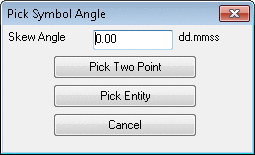
Symbol Angle: When the Symbol Rotate value is set to
Enter Azimuth Angle, use this field to specify the
rotation angle for the symbol, or pick using the screen pick
icon

If selecting the icon for symbol rotation the follow options are
available for use.
Symbol Size: Indicate how the size of the symbol should be determined:
Rim Elevation: Indicate the rim elevation for the structure.
Depth: Indicate the distance between the Rim Elevation and the base (bottom) elevation of the structure.
Invert-Out Elev: Indicate the invert elevation of the pipe that exits the structure.
Invert-In Elev: Indicate the invert elevation of the pipe that enters the structure.
Drop Across MH: Indicate the amount of vertical drop across the manhole/structure.
Sump Height: Indicate the sump distance below the manhole bottom.
Surcharge Depth: The distance between the hydraulic grade line and the Rim Elevation. If the value is negative, the hydraulic grade line is below the rim elevation; otherwise, the water has blown out the structure.

Current Structure: The Structure Name from the Structure tab that is current. Use the Up, Down or Edit buttons to navigate through the network to set an alternate structure current.
Input Type: If the Computation Method option located in the Drainage tab of the Sewer Network Settings is set to Peak Discharge, then this option is disabled. If the Computation Method is set to Hydrograph, two input types are available:
Area Units: Choose a unit to display the area values.
Draw: When this button is clicked, a watershed analysis is performed on the surface model and the drainage area that contributes to this inlet is hatched in the drawing.
Drainage Area: The drainage area that contributes to this inlet only.
Pick: Use this button to select a closed polyline that represents the boundary of the drainage area. The area will be calculated and displayed.
Calc: This function triggers the watershed analysis routine to calculate the drainage area and weighted runoff coefficient (curve number for SCS method) and displays the values.
Time to Inlet: Indicate the time to inlet or click on the Set button to calculate the Time of Concentration.
Runoff Coeff: Indicate the runoff coefficient or click the Select button to derive a weighted runoff coefficient from land uses and their respective areas. Please refer to the documentation on Define Runoff Layers for details.
Pond/Swamp Adjust: When the Hydro Methods option located in the Drainage tab of the Sewer Network Settings is set to SCS, indicate the Pond and swamp adjustment factor used in SCS peak flow calculations.
Known Flow: You may elect to let any known flow enter into the downstream pipe directly or go through the inlet by enabling the Thru Inlet toggle. This provides flexibility to input the calculated drainage runoff directly to the program and to also enter known sanitary flow, infiltration/exfiltration flow, etc, into the sewer network.
Thru Inlet: When enabled, the known flow will enter the sewer network through the inlet rather than simply being considered system flow, and inlet calculation is conducted. Depending on the inlet capacity, some known flow may be bypassed and flow to the downstream inlet. Otherwise, all the known flow is added to the network flow directly.
In Hydrograph: When the Input Type is set to Hydrograph, use the Select button to specify the Runoff Hydrograph file name (.HYD) that enters into the structure.
Long Slope: Enter the longitudinal slope of the pavement. This edit field is only available if the inlet is "on-grade."
Cross Slope: Enter the pavement cross slope.
Calc: This function triggers the watershed analysis routine to analyze the surface model and extract the longitudinal slope and cross slope.
Manning's n: Indicate the Manning's n-value for the pavement or click on the Library button to retrieve this value from the Pavement Manning's n Library.
Next Inlet for Bypass: Indicate the inlet that shall receive any by-pass flow from current catch basin.
Flow Calculation:
After you issue either the Design or the Analyze command on the network, the inlet
calculation results are displayed. The inlet results help you to
determine if the inlet is sufficient for conveying the ground flow
into the network.

Pipe Name: Provide a unique value to identify the pipe in the network.
Downstream (Upstream) Connections: A list showing the connection that exits the structure or the connection(s) that enters the structure, depending on the Direction setting found on the Design tab of the Sewer Network Settings.
Available: A list that contains all of the structures that are not connected to the current structure, i.e. the potential structures that can be connected to the current structure.
Add: Select an available structure to connect to the current structure and click on the Add button to form the connection.
Pick: Select a structure symbol in the plan view graphic to form a connection between it and the current structure. If the connection cannot be completed, a warning message appears.
Remove: Highlight a connection in the Downstream (Upstream) Connections list and click on the Remove button to remove the connecting pipe between the structures.
Pipe Material: Select the pipe material or click on the Library button to select a pipe and its corresponding Manning's n value from the Pipe Manning's n Library.
Pipe Shape: The pipes can have four different cross-sectional shapes:
Refer to the Pipe Size Library for additional details.
Pipe Size: If the Auto Set All Sewer Pipe Sizes option found on the Design tab of the Sewer Network Settings dialog box is disabled, select the desired pipe size from the list of available pipe sizes or click on the Library button to access the Pipe Size Library.
Design: When enabled, the program calculates an appropriate pipe size based on the flow and design settings and selects the closest available pipe size from the Pipe Size Library.
Pipe CL: This option allows you to design a curvilinear (non-straight) pipe. The pipe centerline should start from one structure and end at the other structure exactly. Use the Select button to identify a Centerline File or polyline in the drawing that represents the pipe path. When one of the structures is relocated, the pipe centerline association will be removed. The pipe bending loss is computed for pipe friction loss when the pipe is curvilinear.
Down Invert/Up Invert: If the Auto Set All the Invert Elevations of the Sewer Network option found on the Design tab of the Sewer Network Settings dialog box is disabled, indicate the upstream and/or downstream invert elevation of the current pipe or enable either Design toggle to have the program calculate the design invert elevation(s).
Slope: If neither the Up Invert Design toggle nor the Down Invert Design toggle is enabled, indicate the pipe slope. Changing the Slope value will alter the Up Invert value unless the Hold Upstream toggle is enabled.
Step Up: Indicate the "step up" amount of the Downstream
Invert elevation with respect to the "invert out" elevation of
the structure to which it connects. In general the invert out
elevation is lower then the invert in elevation of the structure as
water flows from upstream to downstream. In Carlson 2018, we
introduced negative step up in network design, when the
invert out is lower than the invert in at the
junction.
Hold Step Up on Invert Edit: This toggle will hold the step up when editing inverts.
Hold Slope: This option will hold the pipe slope when editing inverts and step up values..
Out Hydrograph: When the computation method is hydrograph, you are able to
generate the outflow hydrograph at the outlet of each pipe. Use the
Select button to specify the file
name.
After you issue either the Design or the Analyze command on the network, the pipe calculation results are shown.
Pipe Flow: Flow that is being carried by the pipe:
Total Area: Total of all the drainage areas that contribute to the flow inside the pipe.
Length: The length of the pipe based on the Pipe Length
setting found on the
Display tab of the Sewer Network
Settings.
Properties and values may also be entered
in the following
Manning's n: Indicate the Manning's n coefficient is used to calculate the friction loss of the pipe.
# of Barrels: Indicate the number of pipe barrels that can be found between the Upstream and Downstream structures.
Hori. Spacing: Indicate the amount of horizontal spacing between each of
the Barrels.

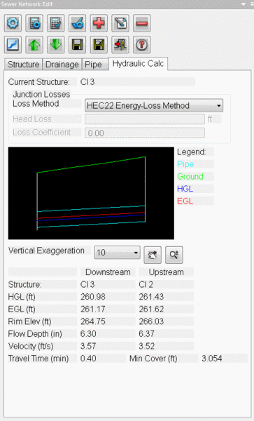
The energy losses through a pipe junction are specified in the Hydraulic Calc tab. There are six methods to calculate the junction losses: Approximate Method, Dynamic Method, Fixed Head Loss and Energy-Loss Method.
Junction Losses: Indicate one of the following methods for junction loss consideration:
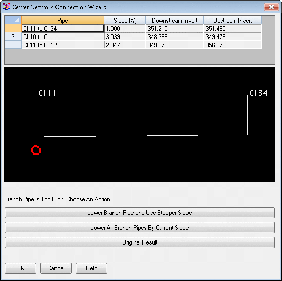
After you run either the Design or the Analyze command on the network, the hydraulic calculation results are displayed. The hydraulic grade line, energy grade line, flow depth, flow velocity at both downstream and upstream ends are reported, Travel Time, which is how long the flow takes to travel through the pipe, and Min. Cover, which is the minimum distance from the surface elevation to the crown elevation along the length of the pipe.
A graphic box also shows the hydraulic and energy grade lines, pipe outlines and the ground surface, which help you to observe the design result easily.
Select sewer structure to edit: Pick a manhole symbol.
Pulldown Menu Location: Network
Keyboard Command: editswr
Prerequisite: A sewer (.SEW) file