
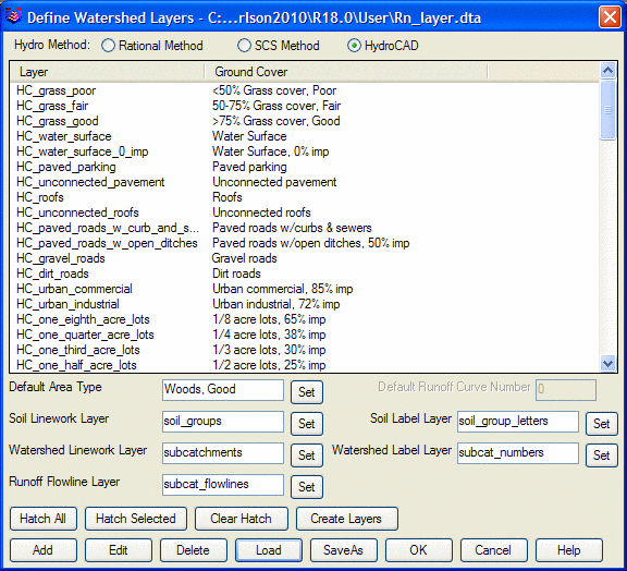
Adding or editing a layer brings up the next
dialog:
This dialog box is the interface to assign specific Ground
Covers to closed polylines in a drawing, based on their drawing
layers. There are 3 modes of operation; Rational Method, SCS
Method, and HydroCAD.
With the dialog set to Rational Method, the runoff coefficients
are the C-Factors in the Rational Equation Q = C*I*A. Q is
flow, I is rainfall intensity and A is area. The Rational
Method is often used for urban and residential flow analysis.
For example, building layers can be assigned a high runoff
coefficient (C factor) such as 0.85 and wooded areas would be
assigned a low runoff coefficient such as 0.20.
With the dialog set to SCS Method, the coefficients are set to
values from 0-100, so Roofs might be 85 and Woods 20. A Soil
Type must also be specified for each Ground Cover.
With the dialog set to HydroCAD, the runoff coefficients are not
set at all, but are added when the data is exported to
HydroCAD.
With the Rational or SCS Methods, the runoff coefficient area
polylines are used to determine the weighted runoff coefficients
for drainage areas in conjunction with other Carlson Hydrology
commands such as Watershed Analysis and Edit Sewer Structure. The
runoff coefficient polylines are automatically clipped by the
drainage perimeter polyline to find the coefficient sub-areas
within the drainage perimeter. Therefore, it is important to
close all polylines, use distinct layers for features that have
distinct runoff values, and to assign a runoff coefficient to the
unassigned, "remainder" areas. It is also important to
enclose areas beyond the site with closed polylines and assign
runoff coefficients to those layers to account for the off-site
water entering the site.
Looking at Rational Method first, the initial dialog box would
look something like this:


The Create Layers button creates the
layers from the list in the current drawing. All layers can
be created, or certain layers can be selected before picking the
Create Layers button and you can specify to create only the
selected layers.

The Color TIN button applies the colors defined for the ground
cover areas to colorize a triangulation file which is helpful for
visualizing the surface in 3D viewers.
There are settings for the default area name and default
coefficient that are used for any part of the drainage area that is
not covered by one of the runoff layer polylines.
The Soil layers are optional for finding the soil sub-areas
within each runoff sub-area. These Soil layers are used in commands
that calculate the runoff sub-areas within a watershed boundary
such as the Select Watershed function within the Curve Numbers
& Runoff command. When the Soil layers are assigned, the
program will get all the linework on the Soil Linework layer to
build a topology of the soil areas. The linework does not need to
be made of closed polylines but the linework collected together
should enclose the soil areas. Then the program takes the text
entities in the drawing that are on the Soil Label layer. The text
is used to identify the soil group. The first character in the text
should be A, B, C or D for the four soil groups. The program looks
for the text to be within the soil area to assign the soil group to
that area.
The Watershed Linework layer is used in commands for selecting
the watershed area by picking a point within the area. For
instance, the Select Watershed routine in Curve Numbers &
Runoff will prompt whether to select by perimeter (closed polyline)
or interior point (watershed layer method), when the Watershed
layer is defined. Similar to the Soil Linework layer, the program
will get all the linework in the drawing that is on the Watershed
layer and build a topology of the watershed areas. The linework
does not need to be made of closed polylines but should make closed
watershed areas when taken together. When you pick the interior
point, the program finds the watershed linework that encloses the
point to get the watershed perimeter.
The Watershed Label layer is used by the Hydro Network commands
to match the drawing watershed area with the subcatchment node in
the network. The match is between the value of a text entity on the
watershed layer with the name of the subcatchment node.
The runoff polyline areas use region logic where a polyline
inside another on the same layer is used as an exclusion. A
limitation is that polylines on the same layer must not
intersection each other. For polylines on different layers, there
can be polylines within other polylines and for any given point,
the smallest enclosing polyline is used to determine the runoff
coefficient.
Example 1: In the example below, the site perimeter polyline is
on the Regions layer, the building pads are on the Pads layer and
the edge of pavement polylines are on the Roads layer. All these
polylines are closed polylines. The areas within the buildings are
inside both the Region and Pads polylines and the Pads govern
because they are the smaller area. Likewise the road areas are
governed by the Roads layer and road interior islands are not
counted for Roads because the interior Roads polyline acts as an
exclusion perimeter. The rest of the area is set to the Regions
layer.


Buildings, roads, driveways, lot lines and wooded areas are in distinct layers. As soon as the command is selected the dialog below appears. The applicable layers can then be organized as follows within the command. Note that the lot lines do not have any hydrology impact and are not included in the layer-runoff coefficient assignment.

Example 1 used the built-in logic to remove closed polylines from outer enclosing closed polylines. So in the example 2 case, the overall property boundary had a runoff coefficient of 0.2 that was assigned its runoff coefficient by layer, and all other assigned closed polylines found within it (roads, buildings, driveways) will be calculated distinctly. For example 2, the entire "remainder" area that is not assigned and is given a default runoff coefficient, such as 0.5 shown above. Therefore, within any site perimeter, both the "unassigned" method for remainder areas or the assigned, outer boundary layer method for the remainder areas can by used. When the "Hatch All" button is clicked, the drawing will hatch in the defined colors and layers, as shown below:
