Input-Edit Section File
This program can be used to enter or edit data stored in a section
file (.SCT file), including a real-time graphic window in the Edit
mode. The section data consists of stations, offsets, elevations
and descriptions. This command also has utilities for translating
the offsets and elevations, deleting stations from the file,
intersecting the outslopes of one section file with another,
combining multiple occurrences of the same station and sorting the
stations, offsets and elevations.
While editing the section file, a second section file can be used
as reference. To choose this file, pick the 2nd button. For
example, when editing the proposed section file, you can reference
and view the ground section file as the second file. Besides
showing the reference section in the graphic preview, the program
also reports the end areas while editing a section station. Also,
the reference section can be used to tie to the catch point.
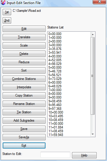
The program begins by prompting for a New or Existing section
.SCT file to process. The Section file to process dialog appears,
allowing you to specify the file that you want to operate on. Use
the New option to create a new file. Use the Existing option to
edit the offsets and elevations for station/sections that you have
already created, or append new stations to a file. The program
defaults to a section file with the same name as the drawing or a
name that you specified using another section command. You also can
choose a 2nd existing .SCT file to reference. After specifying the
file name(s), the program displays any stations currently in the
file, in the Stations List of the Input-Edit Section File dialog
box.
Alternately, when sections are drawn in the drawing, you can
double-click on a section polyline to launch Input-Edit Section
File for the .SCT file associated with the section polyline.
If you specified a new file, the Stations List box will be
blank. To edit and display the offset and elevation data at a
station, you can double click on the station in the Stations List
box, or input the station in the Station to Edit edit box at the
bottom of the dialog. To add a station to a new file or existing
file, you must enter the station in the Station to Edit edit
box. Stations will present in accordance with the
Section-Profile settings in Configure under the Settings pulldown
menu (eg. 10+00, 1+000, 1000).
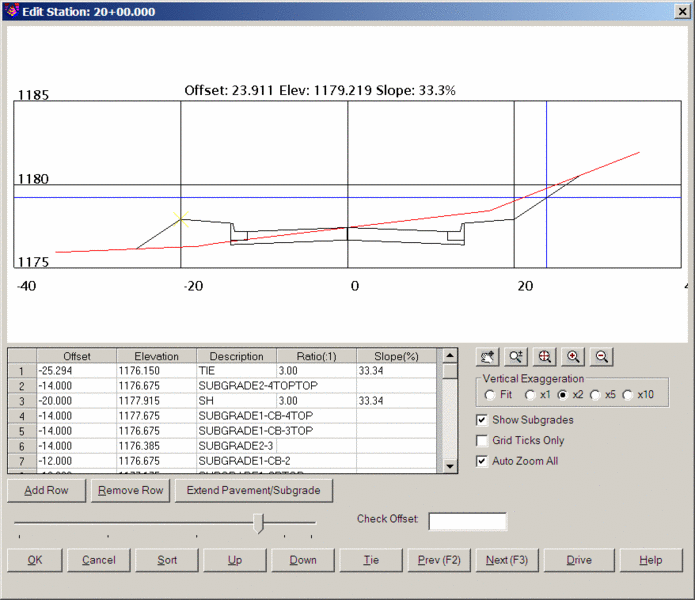
 Edit:
Opens the Edit Station dialog which shows a graphic of the section
on top, a list of the offset-elevation points in the middle, and
the function buttons on the bottom. To add an offset point, type in
the offset, elevation and optional description in the spreadsheet.
Left offsets are entered as negative numbers. You can enter the
slope or ratio from the last point and the program will calculate
the elevation. To edit an offset point, highlight the point
from the list and then edit the values in the Offset, Elev and Desc
columns. The highlighted point will be marked by an X in the
graphic screen. The Sort button will sort the list of offsets
from lowest to highest, left to right. It is recommended that you
Sort offsets before doing the Tie command, so that the left-most
and right-most offsets appear first and last in the offset
list. The Up button will move the highlighted offset point up
in the list. Likewise the Down button moves the highlighted offset
point down in the list. Prev (F2) and Next (F3) buttons move
through the stations and allow you to review and edit stations in
forward or reverse order. The scroll bar can also be used to
quickly move through stations and then zero in with Prev (F2) or
Next (F3).
Edit:
Opens the Edit Station dialog which shows a graphic of the section
on top, a list of the offset-elevation points in the middle, and
the function buttons on the bottom. To add an offset point, type in
the offset, elevation and optional description in the spreadsheet.
Left offsets are entered as negative numbers. You can enter the
slope or ratio from the last point and the program will calculate
the elevation. To edit an offset point, highlight the point
from the list and then edit the values in the Offset, Elev and Desc
columns. The highlighted point will be marked by an X in the
graphic screen. The Sort button will sort the list of offsets
from lowest to highest, left to right. It is recommended that you
Sort offsets before doing the Tie command, so that the left-most
and right-most offsets appear first and last in the offset
list. The Up button will move the highlighted offset point up
in the list. Likewise the Down button moves the highlighted offset
point down in the list. Prev (F2) and Next (F3) buttons move
through the stations and allow you to review and edit stations in
forward or reverse order. The scroll bar can also be used to
quickly move through stations and then zero in with Prev (F2) or
Next (F3).
The section data can be edited directly in the spreadsheet or
graphically by picking the Edit Point button with the pencil icon.
To edit graphically, use the click-n-drag method. Start by picking
the Edit Point button and then pick the section point to edit in
the graphic preview and hold the mouse button down and then drag
the mouse to the new position and then release the mouse button.
The Edit Mode setting governs the click-n-drag operation. The Free
mode allows the section point to be moved anywhere. There Hold
Slope modes maintain the slope and moves the point along these
slopes. The Hold Offset allows changing the section point elevation
only. The Hold Elevation allows changing the point offset
only.
The Add Row button inserts an offset line above the currently
highlighted row. The Remove Row button erases the highlighted
offset and elevation from the list. After inputting or editing
press the OK button to return to the Stations List dialog and keep
any changes you have made. Select the Cancel button if you want to
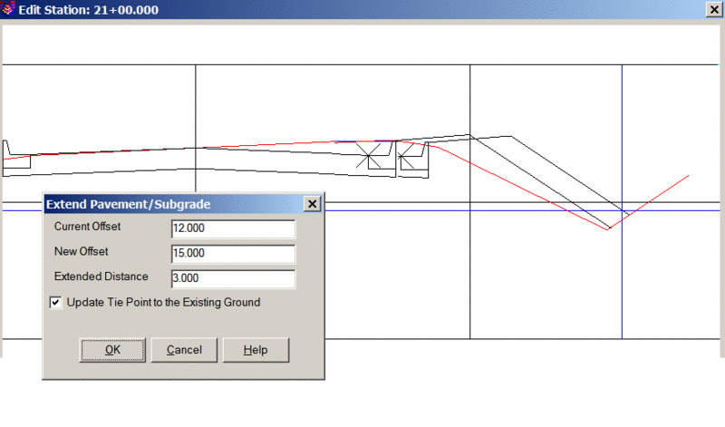
cancel changes made to the current station. Extend
Pavement/Subgrade will allow you move a surface point and shift, in
parallel, the associated subgrades and tie points. One
application, shown below, is to extend a shoulder point and
re-computer the TIE point, all in one clean operation:
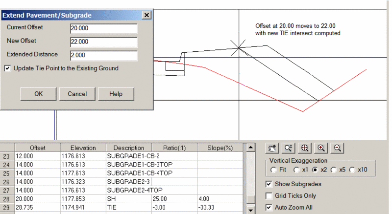
Another application of Extend Pavement/Subgrade is to move the
curb position and all associated subgrades. The "inside" curb
point is at 12.00 units from centerline. If the pavement is
extended from 12 to 15 at this station, use of this feature will
extend the subgrades, maintain all slopes and re-compute the TIE
point, as shown below:
A real-time report of offset-elevation-slope now displays in the
top of the graphic as you move the cursor across the section in the
graphic window. The screen defaults to zoom mode where
holding down the right-mouse button zooms in and out. You can
also switch to pan mode. There are buttons for zoom extents,
zoom in and zoom out. If your mouse has a scroll button, you
can hold it down to pan and scroll it to zoom in and out. You
can also set the Vertical Exaggeration ranging from 1X to 10X and
including "Fit". Show subgrades has the ability to tie a
subgrade into the surface. Grid Ticks Only just shows the
left and bottom axis lines of the grid with grid tick marks along
the axes. With Auto Zoom All turned off, you can hold the
same view position as you click Next and Previous and move through
the list of stations. The Check Offset field calculates an
elevation based on an entered offset.
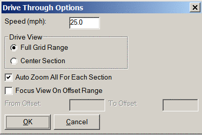
Drive (Edit
Station): This function scrolls through the sections at the
rate of speed specified by the user in the Speed window. The Drive
View options determine whether the sections are displayed using the
full width of the graphic window or centered in the
window. The combination of Full Grid Range and Auto
Zoom All allows the sections to rise and fall with the centerline
elevations, as if you were driving an actual road. With
Auto Zoom All off, and Full Grid Range on, the grid itself moves up
and down at the current position of the first section, as you
drive. Focus View On Offset Range allows the user to set the
left and right viewing limits of the sections. Section data beyond
the specified limits is not displayed.
Elevation Field (Edit
Station): Equations (+, -, *, /) can be entered to calculate
or adjust an elevation. For instance, to subtract 1.25' from
elevation 1926.18, simply enter 1926.18-1.25 and press enter. The
new elevation will be calculated and displayed in the viewer
window.
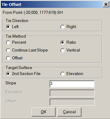
Tie (Edit Station): The
Tie button allows you to tie the left and right surface points of
the 1st section file into the 2nd section file. It is used
for classic outslope intersects from final grade to existing
grade. The dialog layout includes an option to tie the
section to a specified elevation, in addition to a surface (second
section file). A left or right tie direction can also be
selected. If a point has been tied in from SH for shoulder at
offset -20 at 3:1, a new offset with the description "TIE" is
created. If you try another outslope such as 4:1 from the
same SH shoulder point, a new "TIE" point is created and the old
TIE point is removed automatically.
 Lock:
Lock: This function will tag the
section file as locked so that no routine can automatically
overwrite this file. If a routine attempts to overwrite this
section file, the program will stop, report that the file is locked
and prompt whether to override the lock.
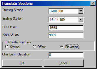
Translate: Allows you to add or subtract a distance from the
offsets to adjust or shift the centerline. You can also adjust the
elevations up or down. When using this option, you can choose the
range of stations to operate on (starting and ending stations) and
the values to adjust the offsets and elevations. If, for example,
you want to shift the centerline, but not the elevations, enter the
plus or minus amount you want to translate, and when prompted for
the elevation enter zero.
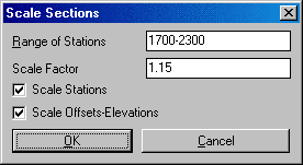
Scale: Allows you to scale the station, offsets and/or
elevations by the specified scale factor. This function can be used
to convert between English and metric units.
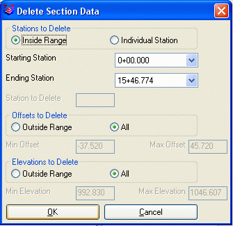
Delete: Allows you to remove a station or range of stations
from the Stations List. You can delete a range of stations or an
individual station. Also there are options to delete all the data
for the selected stations or filter to delete only data that is
outside an offset or elevation range. Since the station editor data
is stored in memory, if you accidentally delete a range, Quit the
editor without saving the stations to disk. Then recall the
original file.
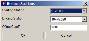
Reduce: Allows you to remove offsets from a range of
stations by removing vertices in the offsets that are virtually in
a straight line. Using an offset cutoff, meaning no offset
and elevation moves more than the entered amount (eg. 0.01),
excessive numbers of vertices can be eliminated. The command
is similar to Reduce Vertices when applied to the plan view.
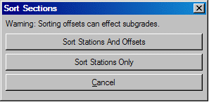
Sort: Allows you to sort the
station numbers into ascending order, and sort the offsets and
elevations in the individual station records (offsets are sorted
from left to right). When sections are derived from the Sections
from Surface Entities command they are already sorted, but when
sections are digitized or input manually they occur in the order
that you digitized them. So, for proper plotting and earthworks,
you may want to run the Sort option before processing.
Combine Stations: Used to
bring together in one record slot multiple occurrences of the same
station number. This can occur when using the Digitize Sections
(XSec) command and the section that you are digitizing has
match/break lines which forces you to digitize the station in two
or more parts.
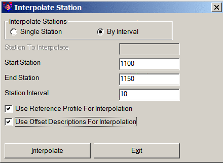
Interpolate: Allows you to add or overwrite a station
between two stations or projecting forward from two stations. You
can choose to interpolate a single station or an interval of
stations. Specify the two known stations in the Start Station
and End Station edit boxes, as well as the interval if using the
interval method. The program will do straight line, mathematical
interpolations, adding offsets to the interpolated stations to
match the totality of offsets in the starting and ending
stations. However, if the offsets have descriptions, you can
choose to interpolate by description and the program will
interpolate by description (eg. EP at 12 on Station 1100 and EP at
15 at station 1150 would lead to EP at 12.6 at 1110). There
is also an option to reference a profile, so if station 1100 and
1150 were on either side of a high point at 1125, the interpolated
offsets would respect the profile as well as the starting and
ending station. Use of this command is often critical to
creating accurate digital terrain models of sites for machine
control. Select the OK button to execute the function with
the current settings or select the Cancel button to abort the
process.
 Copy Station:
 Allows you to copy a
station that already exists to a new or existing station number.
Choose the existing From Station using the edit pulldown box, then
enter the new station number in the To Station edit box. Select the
OK button to execute the function with the current settings, or
select the Cancel button to abort the process.
Rename Station: Allows you to change the value of a
station. In the dialog, select the existing station from the list
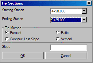
and enter in the new station value.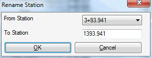 Tie Station: Allows you to tie the outslopes
into the reference second section file. This routine first brings
up a dialog to specify the range of stations to process. It
includes a line to set the slope to tie with. The program will
start from the left most offset and use this slope to find the
intersection with the reference section file. Then the intersection
from the right most offset is calculated with this slope. These
intersection points are the tie points. The slope can be defined by
percent, ratio, continue the last slope, and vertical.
Tie Station: Allows you to tie the outslopes
into the reference second section file. This routine first brings
up a dialog to specify the range of stations to process. It
includes a line to set the slope to tie with. The program will
start from the left most offset and use this slope to find the
intersection with the reference section file. Then the intersection
from the right most offset is calculated with this slope. These
intersection points are the tie points. The slope can be defined by
percent, ratio, continue the last slope, and vertical.
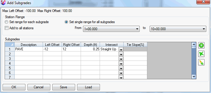
Add Subgrades: Adds subgrades to the sections with
specified depths and offsets. You can add multiple subgrades at a
time by filling in the spreadsheet. Each row of the spreadsheet is
for a separate subgrade. Each subgrade definition takes a
description, left and right offsets, depth and intersection method
of either straight up or at a specified slope. The subgrades are
added by referencing the existing surface elevation and dropping
down the specified depth. The center of the subgrade always drops
down vertically. The outside of the subgrade ties in by the
specified intersection method. The station range to add the
subgrades can be the same of all the subgrades or specified
separately for each subgrade.
 Save: Saves the currently
loaded section file.
Save: Saves the currently
loaded section file.
SaveAs: Allows you to save the currently loaded section file
as a different file.
Exit: Allows you to exit from the section editor and return
to the drawing editor. The program will warn you to save to a file
if you have made changes.
Pulldown Menu Location: Sections
Keyboard Command: scted
Prerequisite: None