
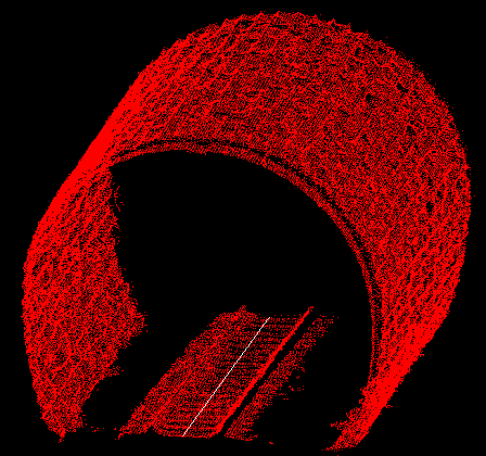
This example of a tunnel shows the input points in CAD along with the alignment polyline along the center of the train tracks and then the resulting solid model viewed with color by normal.
This command creates a solid model from a collection of x,y,z
points and an alignment polyline using the 3D triangulation. The
points need to cover all sides of the surface (top, bottom, left,
right). The alignment polyline needs to be a 3D polyline that goes
through the center of the points for the entire length.
Min Edge Length: Sets the minimum length of a triangle edge
in the solid. When there are several points closer than this
distance to each other, some of these points will be left out of
the solid model.
Max Edge Length: Sets the maximum distance for 3D
triangulation to connect points.
Boundary Method: controls how tightly the solid model wraps
around the perimeter points.
Simplify: removes points that cause steep triangles.
Apply Advancing Front: expands the solid by adding triangles
to unconnected edges.
Fill Holes: triangulates across small holes in the
solid.
Display Solid in 3D Viewer: automatically runs the View
Solid command with the model results.
This example of a tunnel shows the input points in CAD along with
the alignment polyline along the center of the train tracks and
then the resulting solid model viewed with color by normal.

Make Solid dialog
Select alignment polyline: pick 3D polyline
Select points to process.
Select objects: pick points
Solid File To Write Select MDL file
Pulldown Menu Location: Solid
Keyboard Command: pt3dtunnel
Prerequisite: points
| Converted from CHM to HTML with chm2web Standard 2.85 (unicode) |