Vehicle Path Tracking
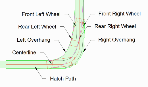
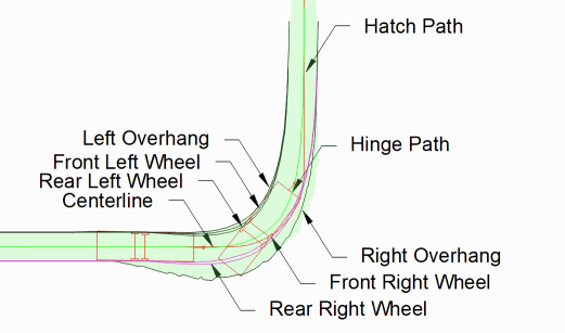
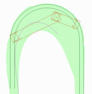
This command traces the wheel paths
for vehicle dimensions along a centerline. The centerline is
defined by a polyline which must be created before running this
command. The front axle follows this centerline based on the path
settings from the Path tab. After specifying the vehicle dimensions
and draw options in the command dialog, the program prompts for the
centerline polyline and then draws the paths.
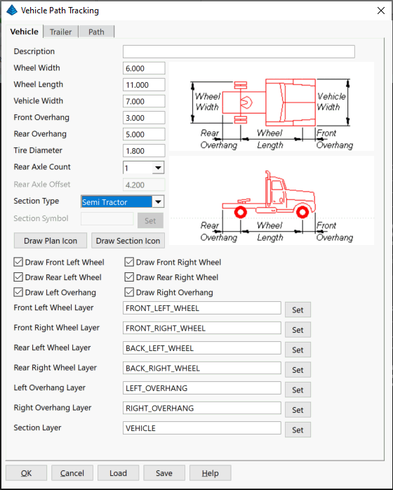
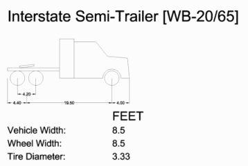
Vehicle
For the vehicle settings, pick on the Vehicle Tab. These are the
set of dimensions for the vehicle and separate layers for the
vehicle points to track.
Description: Description of
the Vehicle Path Tracking command settings if saved. (Optional)
Wheel Width: Distance along
the wheel axis to the outside of the tires.
Wheel Length: Distance
between the front axle and rear axis.
Vehicle Width: Outside
width dimension of the vehicle body.
Front Overhang: Distance
from front axle to front of vehicle body.
Rear Overhang: Distance
from rear axis to the back of the vehicle body.
Tire Diameter: Outside
diameter of the vehicle tires.
Rear Axle Count: Number of
rear axles.
Rear Axle Offset: Distance
between rear axles.
Section Type: Section List
for Vehicle types.
Section Symbol: Symbol to
represent the vehicle.
Set: Select the
corresponding vehicle symbol.
Draw Plan Icon Select
location and places plan view detail of Vehicle in CAD.
Draw Section Icon Select
location and places section view detail of Vehicle in CAD.
Draw Front Left Wheel:
Draws the front left wheel path.
Draw Front Right Wheel:
Draws the front right wheel path.
Draw Rear Left Wheel: Draws
the rear left wheel path.
Draw Rear Right Wheel:
Draws the rear right wheel path.
Draw Left Overhang: Draws
the left overhang of the vehicle path.
Draw Right Overhang: Draws
the right overhang of the vehicle path.
Front Left Wheel Layer:
Layer to draw the front left wheel path on.
Front Right Wheel Layer:
Layer to draw the front right wheel path on.
Rear Left Wheel Layer:
Layer to draw the rear left wheel path on.
Rear Right Wheel Layer:
Layer to draw the rear right wheel path on.
Left Overhang Layer: Layer
to draw the left overhang of the vehicle path on.
Right Overhang Layer: Layer
to draw the right overhang of the vehicle path on.
Section Layer: Layer to
draw the details of the vehicle on.
Set: Select the
corresponding vehicle layer from list.
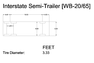
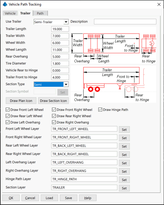
Trailer
For the hinged vehicle settings, pick on the Trailer Tab. These are
the set of dimensions for the trailer and separate layers for the
trailer points to track.
Use Trailer: Use this list
to setup the trailer data and choose paths to draw. Choose None or
between Tow and Semi-Trailer to change the values for easier input
based on semi-trailers or tow trailers.
Description: Description of
the Trailer if saved. (Optional)
Trailer Length: Outside
length dimension of the trailer.
Trailer Width: Outside
width dimension of the trailer body.
Wheel Width: Distance along
the wheel axis to the outside of the tires.
Wheel Length: Distance
between the front axle and rear axle.
Rear Overhang: Distance
from rear axis to the back of the trailer body.
Tire Diameter: Outside
diameter of the trailer tires.
Vehicle Rear to Hinge:
Distance from the rear of the vehicle and the hinge location.
Trailer Front to Hinge:
Distance from the front of the trailer to the hinge location.
Section Type: Section List
for Trailer types.
Section Symbol: Symbol to
represent the trailer.
Set: Select the
corresponding trailer symbol.
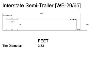
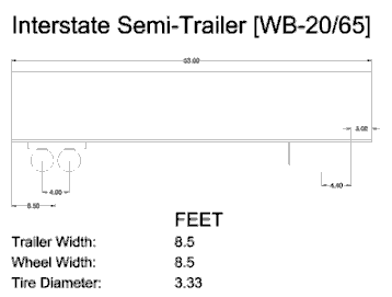
Draw Plan Icon Select
location and places plan view detail of Trailer in CAD.
Draw Section Icon Select
location and places section view detail of Trailer in CAD.
Draw Hinge Path: Draws the
hinge path.
Draw Front Left Wheel:
Draws the front left wheel path.
Draw Front Right Wheel:
Draws the front right wheel path.
Draw Rear Left Wheel: Draws
the rear left wheel path.
Draw Rear Right Wheel:
Draws the rear right wheel path.
Draw Left Overhang: Draws
the left overhang of the trailer path.
Draw Right Overhang: Draws
the right overhang of the trailer path.
Front Left Wheel Layer:
Layer to draw the front left wheel path on.
Front Right Wheel Layer:
Layer to draw the front right wheel path on.
Rear Left Wheel Layer:
Layer to draw the rear left wheel path on.
Rear Right Wheel Layer:
Layer to draw the rear right wheel path on.
Left Overhang Layer: Layer
to draw the left overhang of the trailer path on.
Right Overhang Layer: Layer
to draw the right overhang of the trailer path on.
Hinge Path Layer: Layer to
draw the hinge path on.
Section Layer: Layer to
draw the details of the trailer on.
Set: Select the
corresponding trailer layer from list.
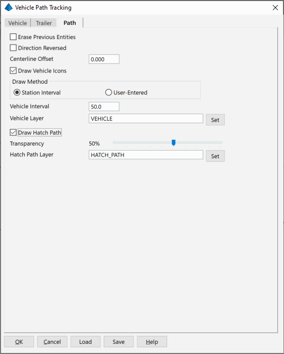
Path
For the path settings, pick on the Path Tab.
Erase
Previous Entities: Removes previously drawn paths for
selected centerline.
Direction Reversed:
Processes the centerline from the end to the start.
Centerline Offset: Distance
from the centerline for the front axle to follow.
Draw Vehicle Icons: Draws
the vehicle and trailer symbols with the specified dimensions.
Draw Method Choose between
placing vehicle symbols at the specified Station Interval along the
centerline or User-Entered for prompting to pick points along the
centerline to place the vehicle symbols.
Vehicle Interval: Interval
distance between vehicle symbols.
Vehicle Layer: Layer to
draw the vehicle and trailer symbols on.
Draw Hatch Path: Hatches
the entire path of the vehicle and trailer along the
centerline.
Transparency: Transparency
applied to the hatch drawn.
Hatch Path Layer: Layer to
draw the hatched path on.
Set: Select the
corresponding layer from list.
The Save and Load buttons save and recall the
vehicle and trailer dimensions to a .VTP file.
Prompts
Draw Plan Icon/Draw Section
Icon
Pick Insertion Point:
pick the point for the
detail
Vehicle Path Tracking
dialog
Select centerline polyline:
pick a polyline
Pulldown Menu Location: Roads - Vehicle Path Tracking
Keyboard Command: auto_track
Prerequisite: Centerline polyline