

HEC-RAS is designed to perform one-dimensional and hydraulic
calculations for a full network of natural and constructed
channels. The Carlson HEC-RAS Manager interfaces directly with
HEC-RAS to seed HEC-RAS with needed surface, alignments,
cross-section and other data for channel analysis and places that
analysis into the Carlson DWG. It is also very convenient because
the output from the program can be exported directly for use
elsewhere. HEC-RAS software is free and can be downloaded from
http://www.hec.usace.army.mil/software/hec-ras/.
You must have version 5.0 or newer downloaded and installed on
your machine to use the HEC-RAS Manager; you must have version 6.0
or newer installed to use the 2D Ras Mapper feature.
HEC-RAS projects require a surface (tin), a Reach Alignment file (mxs) and a Reach Section file (xsct). Import or create a tin. Draw or import a polyline down the center of the channel from downstream to upstream. Use the command editmxs to create or edit the .mxs Reach Alignment file.
The command, hecras, may be typed in the
Command Ribbon or found in the Hydrology module, Watershed
dropdown, HEC-RAS Surface Model, HEC-RAS Manager.

It is used for creating, managing and modifying HEC-RAS projects
directly from Carlson Hydrology. When executed, you will
select or create a .ras HEC-RAS Settings file. Once the .ras
file is chosen or created, the HEC-RAS Manager dialog
appears. Click the Select button to create a new HEC-RAS
project file or to select an existing project. Set the
HEC-RAS version by clicking the dropdown arrow and choosing the
version you downloaded and installed. The .ras settings file is
updated when the HEC-RAS Manager is closed using the "X" or the
exit button.

Select the Create/Update Project button to
update an existing project or to create a new one. When
clicked the Create HEC-RAS Project dialog appears. Use the
Set buttons to assign the Reach Alignment file, the Reach Section
file and the HEC-RAS project name. Fill in the River Name and
the Reach Name. Use the Set buttons to assign the Manning's
friction coefficient (n) to the banks and bottom of the channel.
Choose the Bank Position Method, which determines were the bank is
located. Choices are Percentage of Width, Section Description or
Bank Polylines. If one or more Steady State Flows need to be
included, click the Add button below the box and add Station and
Flow. Once added, you may edit or delete these by
highlighting the flow and clicking the appropriate button
below. Boundary Conditions may be set using the Boundary
Conditions dropdown menus for both Upstream and Downsteam
Boundaries. Choices are None, Known Water Surface, where the user
must fill in a elevation, Critical Depth, Known Depth, where the
user must fill in a slope percentage, and Rating Curve, where the
user inputs one or more Stages (elevations) and Flows. These are
the minimum inputs needed to create a HEC-RAS project. The
HEC-RAS project file .prj, plan file .p01, geometry file .g01 and a
steady flow .f01file are created when the Export
button is clicked. These are the minimum files needed for a HEC-RAS
project. The user is returned to the HEC-RAS Project Manager
dialog after the Export.

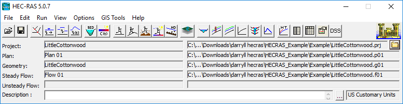
Selecting the Project button calls the main
HEC-RAS project screen, allowing for viewing and editing.
Selecting the Geometry button calls the
HEC-RAS Geometric Data dialog, with tools and editors to add
complexity to the reach.


Use the HEC-RAS Bridge and Culvert
Tabs to add bridges and culverts along the reach. You will
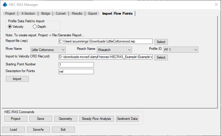
need to re-run the Steady Flow Analysis. Click the Results
tab on the HEC-RAS Manager. Select the Type of results desired and
click Update. The desired results are displayed.


| Converted from CHM to HTML with chm2web Standard 2.85 (unicode) |