


The Advanced Weir Design uses the methodology described in HEC-22 Manual. The weir flow is determined as:
Q = Cw L H1.5 for the Rectangular Weir without Contracted End|
|
|
|
Rectangular Weir with Contracted End |
Rectangular Weir without Contracted End |
|
|
|
|
Trapezoidal Weir |
V-Notched Weir |
This command designs a weir structure and calculates its
stage-discharge curve. Select Weir Design from the Structure menu
in the Hydrology Module to display the design dialog. Select the
Type of the weir , Rectangular, Trapezoidal or V-notched. Enter the
dimension for the weir. In the Invert Elev box, type the absolute
elevation at which the weir will be attached to a reservoir. The
attachment point is at the bottom of the weir. In the Coefficient
box, type a weir coefficient value. In the Number of Openings box,
enter the number of weirs you want to combine.
The program performs two-way calculation: calculate Discharge from Headwater, and calculate Headwater from Discharge. In the Headwater and Tailwater boxes, type the absolute headwater surface elevation and tailwater surface elevation respectively, and the maximum discharge and flow velocity through the orifice would be computed automatically. When Discharge value is entered, the Headwater elevation would be calculated automatically.
Click on the Stage-Discharge Result button to display the
stage-discharge curve in the Stage-Discharge Result Dialog. This
dialog allows you to write the stage-discharge data to a
stage-discharge file(.STG), and draw the stage-discharge curve on
the screen. From the Stage-Discharge Curve Draw Settings dialog,
you can draw the curve into the drawing or write a .stg
stage-discharge file.
The Report Setup chooses between the Standard Report and the PDF
Report. The Standard Report is a simple text report of the
parameters and results. The PDF Report adds some text formmating
and options to draw a schematic of the weir and draw a
stage-discharge graph. The Report button generates the weir design
report.
The Draw button creates a schematic of the weir with dimensions
in the drawing.
The Load and Save buttons store and recall the parameters to a
.weir file.
 |
| Advanced Weir Design
Dialog |

|
| Stage-Discharge Limits
Dialog |

|
| Stage-Discharge Result
Dialog |
|
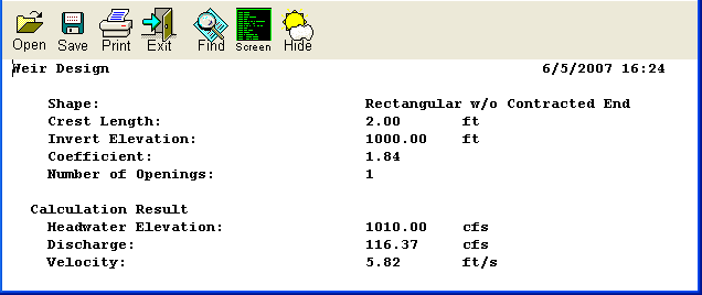
| Weir Design Report |
| Converted from CHM to HTML with chm2web Standard 2.85 (unicode) |