HydroNet Explorer
HydroNet Explorer is a powerful stormwater modeling program that
designs and analyze simple and complex watershed networks. In the
program, you define a hydrologic network by building a collection
of hydrologic nodes. There are four types of nodes: subcatchment,
pond, reach and link.
The general idea for the use of the HydroNet Explorer is that
you have already prepared a drawing for analysis.
This preparation would include:
Soils: The boundaries of the Hydrologic Soils Groups should be
drawn on the drawing layer specified in the Watershed Layers
dialog, with the A, B, C, or D labels on the layer specified for
that. These areas do not have to be closed polylines, as long
as the linework encloses each area that is part of the
study.
Ground Covers: The various Ground Covers in the study area
should be drawn as closed polylines on the layers specified in the
Watershed Layers dialog. These do not need to be
labeled.
Watersheds: The Watersheds (subcatchments) for the site
should be drawn and labeled. It is best to do this with
closed polylines, but it is not essential, as you can use an
alternative method of picking within the area and having the
software define it from drawing linework.
When you run the HydroNet Explorer command, you
are prompted to create a new .HYN file or open an existing
one. This is the file that stores all of the data about the
components in the project.
Project Settings
Once the HydroNet Explorer is open, the first thing you should do
is check the settings for the current project. Pick the icon
with the GEAR on it. In the HydroNet Settings dialog, review
the various tabs containing the settings for the different aspects
of the project.
On the
General tab, choose Runoff Method either Rational or
SCS TR-20, if choosing SCS-TR20 select SCS Unit Hydrograph (options
include Delmarva, SCS Curvelinear, SCS Triangluar (Set Peak
Attenuation Factor), Clark, Snyder) and then select Pond Routing
Method (Stor-Ind), and Reach Routing Method (options include Stor-
Ind, Stor-Ind w. Trans, Muskingum - Cunge, Modified Puls, and
Channel Lag). Set time span. There are two methods to calculate
watershed runoff: SCS TR-20 and Rational method. Set the surface to
be used to provide the average slope for each subcatchment when
using the Curve Number/Lag method.
On the
Subcatchment tab, set the default starting number for
subareas, the default method for Tc calculation, and also set
whether Curve Numbers should be calculated in Carlson Hydrology
(check the box) or in HydroCAD (uncheck the box).
On the
Pond,
Reach and
Link tabs, set the
default starting number for each of these components.


Rainfall Tab
If you want rainfall to be added to the calculations in Carlson
Hydrology, set up the rainfall parameters here. Otherwise the
rainfall data can be added in HydroCAD. In this dialog, you can
enter multiple rain events for reporting. Detailed information
about setting up Rainfall events in Carlson is under the Watershed
section of the Carlson documentation. There is also an icon at the
top of the HydroNet Explorer that you can use to import a Rainfall
event from another HydroNet/HydroCAD project file.
There are three Rational Hydrograph Types in HydroNet: Modified
Rational, Dekalb Rational and Universal Rational methods. Storm
Duration is required for Modified Rational method.
Rational Rainfall
Report Tab
On the Report tab, establish the type of report and the details of
the report that you want for each of the 4 component types. Each
setup button allows for reporting options in detail, drawing option
such as colors, and linetypes.
Report Existing Condition Outflow is to reference
pre-developed runoff values when reporting proposed analysis
results. Set Existing Condition File to to select a HydroNet
file that has pre-developed watershed condition.
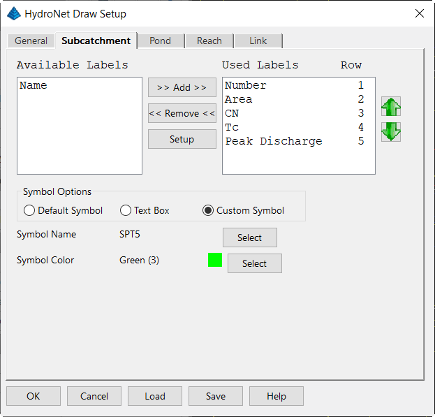
Subcatchment Setup, Pond Setup, Reach Setup, and Link Setup
are used to define detailed reporting options with adjustable
Report Sequence output. Use green arrows to adjust
order.
Report Sequence: This is the order that the hydraulic
components show in the report. The green Up and Down button allow
users to change the report sequence.
Subcatchment
Subcatchment contains the watershed conditions. Once the
watershed layer file is defined by the command Define Watershed
Layers, the program can automatically pull out the watershed data
and fill all the values. There can unlimited numbers of
subcatchment in the network, which are divided by the watershed
boundary polylines.
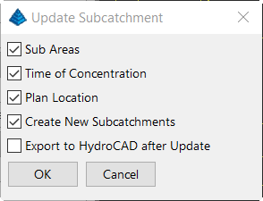
You can now use the HydroNet Explorer to automatically analyze
the drawing and add all subcatchments defined in the drawing.
Pick the Update button, and check all of the options. With
the dialog set up as shown, when you pick OK, all subcatchments
found on the specified layer are added to the Explorer and exported
to HydroCAD. The detailed data for each subcatchment can now
be viewed and/or edited. Double click on any subcatchment to
edit.
To add Subcatchments manually, pick on the Subcatchment item in
the Explorer, and either right click and pick add from the submenu
or pick the Add icon.
In the Subcatchment dialog, enter the Number for the
Subcatchment. If you have the Subcatchment labeled in the
drawing, make the Number match the label. Pick the Edit
button next to the Area. In the Sub Areas dialog, pick the
Select Subcatchment button. Carlson Hydrology searches for a
subcatchment on the layer specified in the Watershed Layers dialog
that has a label that matches on the specified layer that matches
the Number. If it finds one, it highlights it and asks you to
confirm that this is the Subcatchment you are meaning to use.
If you pick Yes, the SubAreas are calculated from all of the
additional data in the drawing. Pick OK. Back in the
Subcatchment dialog, if you specified the CN/Lag method for Tc, the
Average Slope of the Subcatchment has been calculated and
displayed, and the longest polyline within the subcatchment on the
specified layer as been selected and it's length displayed. Define
Baseflow (cfs) if needed. Pick OK. The new Subcatchment
is listed in the Explorer.
Pond
Pond acts as a storage
and routing element in the network, and Reach is a routing element.
The upstream node of pond and reach generates a hydrograph. The
procedure to add Ponds and Reaches is similar to Subcatchments,
either right click and pick Add, or select the category heading and
pick the Add button below. The detailed documentation on
inputting data for these component types is
found in the Watershed section of the Carlson
Hydrology documentation.
Reach
A reach is any length of a stream, river, channel, or culvert. The
term is often used by hydrologists when referring to a small
section of a stream or river rather than it's entire length. User
can select Pick Inlet/Outlet Locations where you will be prompted
to pick Reach Inlet Location or Select Reach 3D Polyline where you
will be prompted to select a 3D polyline. Reach properties
include Invert in, Invert Out, Length. and Slope. Reach Type can be
set to Channel or Culvert with editing options for both.
Reach Type can be set to Channel or Culvert with editing options
for both.

Design Channel

Design Culvert
Link
Link is used to model a hydrograph or a sewer network. This
program assumes that the hydrologic network is a linear system, and
allows two hydrographs to be superposed by adding the two given
flows at a specific time step. In the network two or more
hydrographs are combined at a node by allowing multiple links to
discharge to one downstream node. The procedure to add is similar
to Subcatchments, either right click and pick Add, or select the
category heading and pick the Add button below.
Export to HydroCAD
If you are using HydroCAD in conjunction with Carlson Hydrology,
once the elements of the study are added to the HydroNet Explorer,
pick the Export to HydroCAD button to transfer the data to
HydroCAD.
 Any changes made in the drawing that affect any of the
components of the study can be instantly updated and sent to
HydroCAD with the Update button in the HydroNet Explorer.
Also, each individual component can be updated alone with the
update button within it's specific dialog box.
Any changes made in the drawing that affect any of the
components of the study can be instantly updated and sent to
HydroCAD with the Update button in the HydroNet Explorer.
Also, each individual component can be updated alone with the
update button within it's specific dialog box.
Draw Layout in CAD

The components listed in the HydroNet Explorer can also be drawn
into the drawing file with the Draw Layout in CAD button
(paintbrush). Set the desired parameters in the HydroNet Draw
dialog box.

Setup, Export, Analyze with EPASWMM
Users have the ability to access EPASWMM from within the
HydroNet Manager as well as the EPASWMM command found under the
Network dropdown. You must have EPASWMM on your computer to
use EPASWMM.

The first icon, EPASWMM settings, calls Carlson's EPASWMM
configuration dialogs. The second icon, Export to EPASWMM,
creates a .inp file to be imported at a later time into EPASWMM.
The third icon, Analyze with EPASWMM, directly runs EPASWMM in the
background, creating and displaying the desired report.
Export to HEC-HMS
Users may export data from Hydronet Explorer to HEC-HMS,
Hydrologic Engineering Center - Hydrologic Modeling System. This
software is created by the US Army Corps of Engineers and is used
to simulate the effects of precipitation and runoff of areas with
tributaries. Using three main components - Basin Model,
Meteorologic Model and Control Specifications - each with many
parameters, the user can simulate a wide range of hydrologic
problems, from a large river's tributary system and resulting river
flow to small, urban systems, like a storm sewer network.
Much more information about the abilities, how to use HEC-HMS and
how to download the software is available here:
https://www.hec.usace.army.mil/software/hec-hms/
To export, click the HEC-HMS export icon
Choose the Project Name, Start Date, Start Time, End Date and End
Time. Click Export.
HEC-HMS can also be accessed using simplified inputs not
requiring modeling under the Watershed => Hydrograph Routing
=> Watershed Hydrograph => SCS Method or by typing
"RUNOFFHYD" in the Command Ribbon. Modify parameters as
needed, calculate and click the "HEC-HMS" button to export data for
HEC-HMS input.
Pulldown Menu Location: HydroCAD
Keyboard Command: hydronet2
Prerequisite: Soils, soil labels, watersheds, watershed
labels, a TIN, and Ground Covers, all on different layers for the
different areas.