This command will create a Block Model (.blk file)
from drillholes and channel samples. A .blk file is simply a list
of .grd files that model the variation of some attribute across a
bed (e.g. calcium, magnesium, etc.) or across strata types. Because
the block models are represented by a collection of grid files,
there are some points that should be noted:
When the command is first executed, you will be
prompted to select drillholes and channel samples to use. After
selecting these entities, the below dialog will appear.
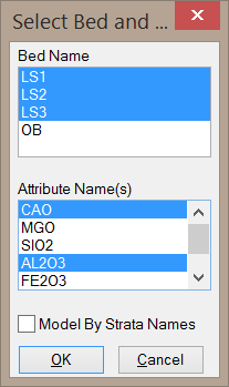
Bed Name: This list will only be populated by beds with
attributes. Note that bed names represent a collection of strata.
When a block model is created from a bed, there will be no
distinction of strata types - all blocks will be treated as being a
part of a single bed. In the above example, four beds with quality
attributes have been detected: LS and OB. You may select multiple
beds for the block model, but it is important to note that the
block model will not keep track of the bed name in the
blocks.
Attribute Name(s): This list shows the attributes
detected within the selected bed. You may include multiple
attributes in a single block model by clicking and dragging within
the list or by holding the CTRL key while selecting
attributes.
Model By Strata Names: This option will create the block
model from selected strata names. This option will tag each block
in the model as having a different Strata Index number. For
example, Limestone blocks may be tagged with a 1, Clay blocks may
be tagged with a 2, Overburden blocks may be tagged with a 3, etc.
This allows you to distinguish between strata types in the block
model rather than treating all blocks as a part of a single bed.
You may still model the variation of some attribute throughout the
model when this option is selected.
This option will prompt you to create a Grade Parameter File (.gpf file) that defines each Strata Index number. It is recommended to do this as it is the only place to keep track of the strata types in the block model.
This option will also prompt you to create a Geologic Model. This Geologic Model will be listed as having a single strata with a block model added to define the variation in the qualities. When modeling by strata names, the block model actually defines the various types of strata, so it is not necessary to define multiple strata layers in the Geologic Model.
After selecting the options on the above dialog, you will be
prompted to select the horizontal extents of the block model by
picking X-Y locations on the screen or by referencing the location
of an existing grid file. After following these prompts and setting
the horizontal extents of the block model, the below dialog will
appear.
Specify Horizontal Resolution As...: This option determines how the size of the cells are defined. The Number of Cells in X and Y option will use the X and Y fields to set the number of cells in the horizontal plane. With this option, the dimensions of the cells will be calculated rather than manually set. The Dimensions of a Cell option will set the cell dimensions using the X and Y fields. If you opt to set the horizontal extents according to an existing grid file, this dialog will not allow you to set the size of the cells in the X and Y directions.
Vertical Position: This option will define the upper and
lower bounds of the block model. The Fixed Elevations option will
use flat elevations as specified by the Bottom Z and Top
Z fields. The Follow Ore Model option will create grid files to
define the upper and lower extents of the selected bed. With the
Follow Ore Model option, the Block Model Method will
determine how the grids are made.
Crop No Grade: This option is only available when using the Follow Ore Model option. When enabled, you will be prompted for a Grade Parameter File (.gpf file) which defines the various grades of material. When making the upper and lower limits of the block model, these grids will only extend to portions of the bed that have been defined within the Grade Parameter File. In other words, any blocks with values not defined in the Grade Parameter File will be cropped out.
Crop Block by Estimated Strata/Bed: This option is only used when the Vertical Position is set to Fixed Elevation. When this option is off, the blocks will be populated with values at all elevations between the Top and Bottom Z. When this option is on, only some blocks will be populated with block values. The program will create top and bottom elevation grids that follow the ore layer, and any blocks outside of this elevation range will not be populated with values. To ensure that all blocks are populated with values, this option should be disabled.
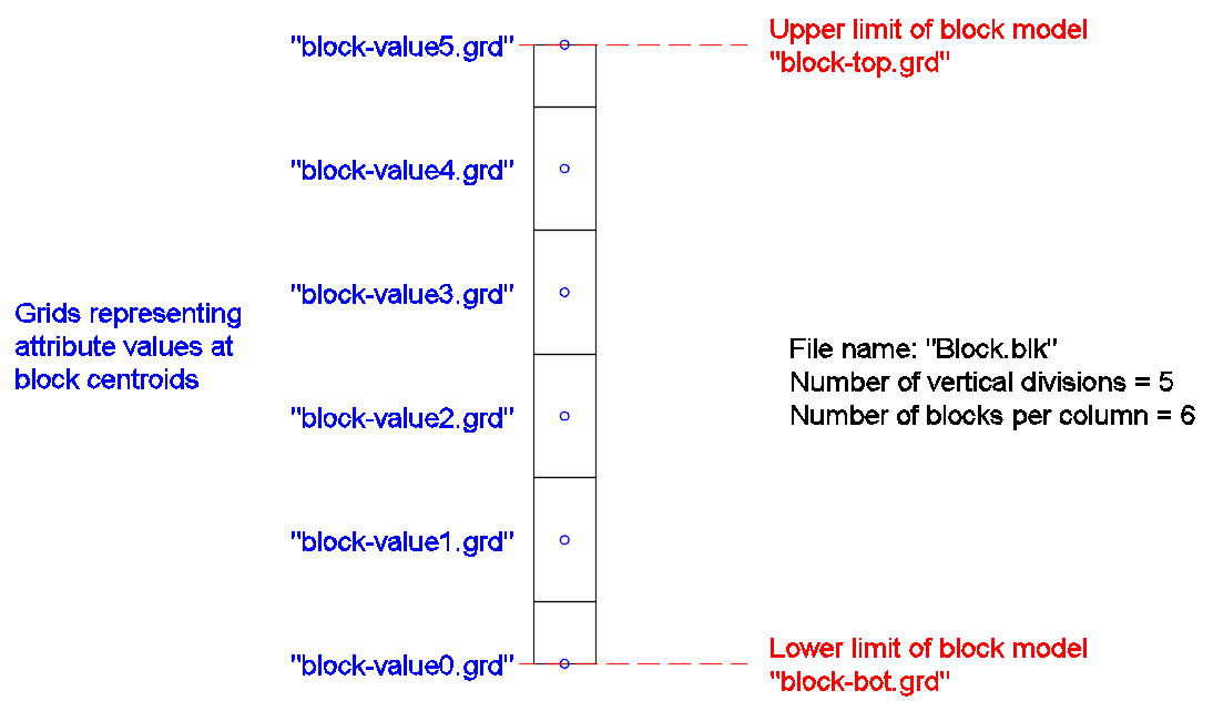
Number of Vertical Divisions: This option controls the
number of blocks per x-y location in the model. If this value is
set to 5, a total of 6 blocks will be present in each column of the
block model. Here it is important to note that the height of each
block will depend on the upper and lower limits of the model. If
these limits are set at flat elevations, then the block height will
not vary with location. If these limits follow the ore model, it is
very likely that the block height will vary with location.
It is also important to note that the top and bottom block of
each column will be half the height of the other blocks. This can
be seen in the image at the bottom of this article. When
calculating reserves with the Surface Mine Reserves command, the
program can apply logic to account for the missing half-blocks at
the top and bottom of the block model. For more information on this
logic, see the section of the help manual corresponding to the
Surface Mine Reserves command (subsection "Report Formatter and
Miscellaneous Notes").
Block Model Method: This option determines which modeling
method is used to create the block model.
For details about each modeling method, see the section of the help manual corresponding to the Make Strata Grids command.
Vertical Weight Factor: When using the Inverse Distance
method as the modeling method, the Vertical Weight Factor can be
used to modify the degree of vertical trending in the deposit. It
should be noted that this value is not the same as the distance
weighting power. When this value is set to 1.0, the model will be
calculated using normal inverse distance weighting. When this value
is greater than 1.0, the vertical distances between the blocks and
the drillhole samples will be exaggerated by the Vertical Weight
Factor to allow for more vertical variation in the model. When this
value is less than 1.0, vertical variation in the model will
decrease. The below diagram and table demonstrates how various
Vertical Weight Factors will impact the relative weight of each
sample on the resulting block value. In this example, an inverse
distance weighting power of 2 is used for all calculations.
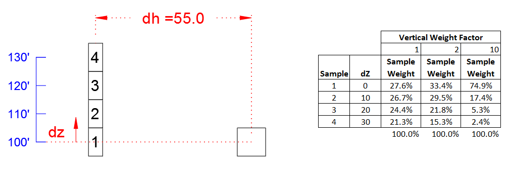
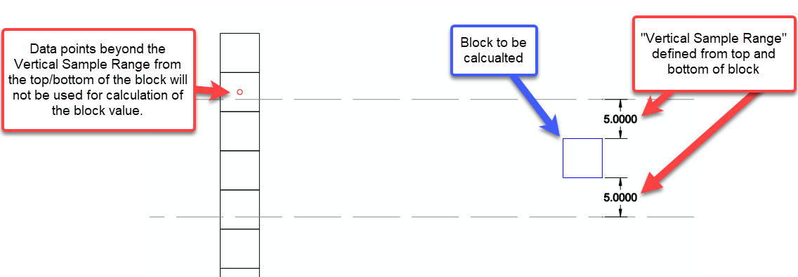
In the above example, there are 4 quality samples in the black drillhole. The example block lies 55' away from the drillhole at a centroid elevation of 100. Each of these 4 samples will be weighted to determine the actual value of the block. The table to the right shows how increasing the Vertical Weight Factor will impact the weight of each sample on the block value. Notice that as the Vertical Weight Factor increases, the weight of Sample 1 on the block value increases significantly, while the weight of Sample 4 on the block decreases significantly. This means that for a higher Vertical Weight Factor, a block's value will more closely resemble that of samples at elevations similar to the block.Vertical Sample Range: This option allows you to limit the vertical distance the program will search for data points when calculating block values. The below image is a visual explanation of this option. It is important to note that this Vertical Sample Range is checked as each individual block in the model is calculated. For each block level, the program finds sample points from the drillhole within the block level elevation range plus this Vertical Sample Range. When this setting is set to zero, the program creates a single composite data point at each drillhole for each block level.
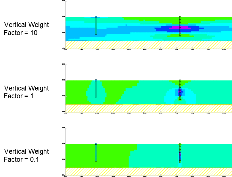
The below images show how a block model can vary simply by modifying the Vertical Weighting Factor. Three values are used for comparison: 0.1, 1, and 10. Notice how the Vertical Weight Factor of 10 creates horizontal trending between the data points, whereas the other two model have decreasing degrees of horizontal trending. Note that when the Vertical Weight Factor is set to a low value of 0.1, there is almost no variation in the qualities in the vertical direction.
After entering the additional prompts, you will be prompted to
give the block model (.blk file) a name. All grids that are created
in addition to the .blk file will be named similarly. For example,
if the block model is named "Limestone", 5 vertical divisions have
been set, and the block model represents the Calcium attribute,
then the below files will be created.
Limestone.blk
Limestone-top.grd
Limestone-bot.grd
Limestone-Calcium0.grd
Limestone-Calcium1.grd
Limestone-Calcium2.grd
Limestone-Calcium3.grd
Limestone-Calcium4.grd
Limestone-Calcium5.grd
The "Limestone-top.grd" file represents the elevations of the
upper limit of the block model.
The "Limestone-bot.grd" file represents the elevations of the lower
limit of the block model.
The "Limestone-Calcium*.grd" (where * is a number) files represent
the calcium content for each block level. Note that when 5 vertical
divisions have been specified, 6 attribute grids will be created.
The attribute grid ending with a "0" represents the calcium content
for the lower-most block in each x-y location of the block model.
The attribute grid ending with a "5" represents the calcium content
for the 6th block from the bottom in each x-y location of the block
model.
If more than one attribute is modeled, an additional set of grids
will be created for each attribute using a similar naming
convention.
The below image shows the side view of a column of blocks with
grid files labeled in their respective positions.
Keyboard
Command: BLKMODEL
Pull-down Menu Location: Geology Module > Block
Model
Prerequisite: Drillholes with a bed name, and variable
quality values that can be vertically modeled.
| Converted from CHM to HTML with chm2web Standard 2.85 (unicode) |