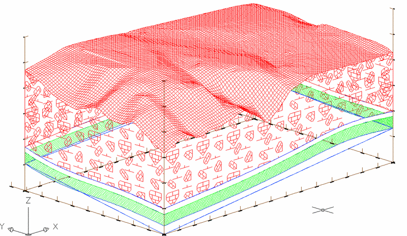
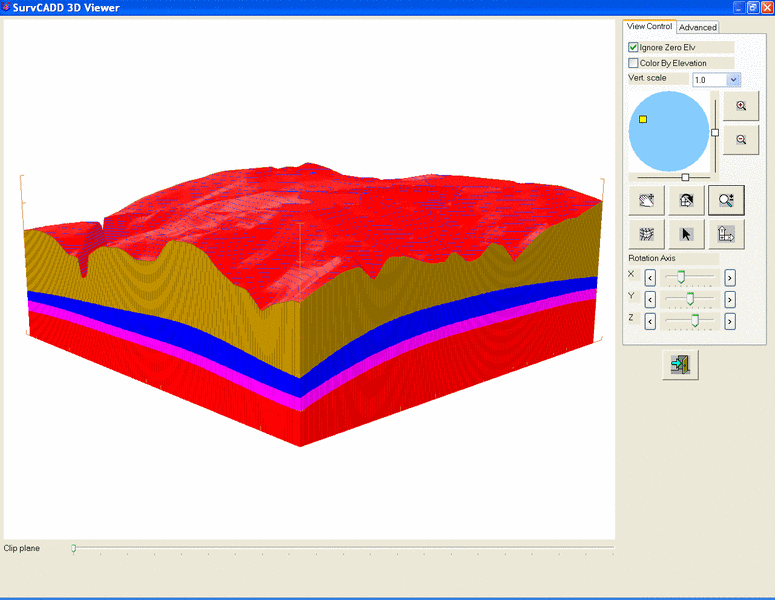
Block Diagram creates a 3D cut out of the site with contours
and/or grid mesh on top and fence diagrams or solid faces on the
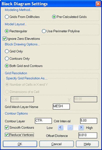
sides. The options for gridding and contours are shown in the first
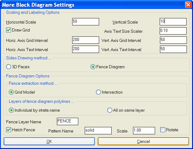
dialog box. The second dialog shows the options for the fence
diagrams and grid. The strata hatch patterns are defined in the
Define Strata command. The default hatch pattern at the bottom of
the dialog is used if there is no pattern defined for that strata.
In order to process a strata for the fence diagrams, there must be
at least one drillhole inside and at least one outside the block
diagram box. This command is basically a 3D Fence Diagram, with
grid faces or contours on top. All of these options are defined in
Make 3D Grid File and Draw Fence Diagram.
Pick or enter Lower Left block corner:
Pick or enter Upper Right block corner:
Reading cell> 194032
Pass> 7 Null Z values left> 0
Calling fence
Drawing strata OVERBURDEN
Drawing strata C1
Drawing strata
PARTING
Drawing strata C2
Drawing grid text
...
Reading cell> 194032
Converting edges ...
Starting contour elevation <4610.0000000>:
Ending contour elevation <4920.0000000>:
Contouring elevation 4920.0000000
Pulldown Menu Location: StrataCalc
Keyboard Command: blockdia
| Converted from CHM to HTML with chm2web Standard 2.85 (unicode) |