Drawing Setup
This command allows you to specify drawing parameters, including
the plotting scale, size of symbols, label annotation size, and the
angle mode.

- Specify English 1in=?ft or Metric 1m=?m as the
unit mode to use. This affects the prompting and reports. When you
are working on a drawing in English units, one unit equals one
foot. In metric, one unit equals one meter.
- Specify the Horizontal Scale of the drawing. For
example, if the horizontal scale is set to 50, then 1" = 50' is
your drawing scale.
- The Symbol Plot Size value is a scaler that represents
the size on the plot. The Drawing Units are determined by
multiplying the scaler by the horizontal scale. In English mode the
scaler represents the plotted size in inches. In Metric mode, this
value is the plotted size in centimeters. The Drawing Units
field shows the result of the Symbol Plot Size value (the scaler)
multiplied by the horizontal scale.
- The Text Plot Size value is a scaler that represents the
size on the plot. The Drawing Units are determined by multiplying
the scaler by the horizontal scale. In English mode the scaler
represents the plotted size in inches. In Metric mode, this value
is the plotted size in centimeters. The Text Plot Size is not
entered in Drawing Units. The Drawing Units field shows the
result of the Text Plot Size value (the scaler) multiplied by the
horizontal scale.
- The Line Type Scaler option sets the linetype scale by
multiplying this scaler by the horizontal scale.
- Angle Mode-Bearing sets reporting to bearing mode for
any of the inquiry commands. (Modifies the settings in the AutoCAD
UNITS command.)
- Angle Mode-Azimuth sets reporting to north based azimuth
mode for any of the inquiry commands. (Modifies the settings in the
AutoCAD UNITS command.)
- Angle Mode-Gon sets reporting to gon mode for any of the
inquiry commands. (Modifies the settings in the AutoCAD
UNITS command.)
- Angle Mode-Other lets the user determine angle mode by
using the AutoCAD UNITS command.
- Coordinate System is an
optional setting to define the drawing coordinate system. The
coordinate system settings are used in commands like List Points
and Label Lat/Lon to report geodetic coordinates from the drawing
coordinates. The Grid System setting applies to drawing coordinates
that are in a grid projection system such as state plane
coordinates. The Projection list selects the grid projection from
the list of supported projections. Along with the Projection, there
are selections for the zone and datum to use with the projection.
When the drawing setup is in English mode, there is a projection
setting for whether the feet are in US Feet or International Feet
units. The Local System setting applies to all other coordinate
system beside grid projections. The Define Localization button has
settings to define the transformation from local coordinates to
grid coordinates. With a localization defined, you can work in a
drawing in local coordinates and still report lat/lon. The
localization definition contains pairs of local and grid
coordinates that define the transformation. See the section on
Localization under the Coordinate File Utilities command for more
information. The Project Scale Factor is multiplied by the x,y
coordinates when converting between drawing and geodetic
coordinates.
- Projection: There are
several built-in projection including State Plane 83, State Plane
27 and UTM. Also on the Projection list is an item for More
Pre-Defined as well as User-Defined projections. This expanded
Pre-Defined selection includes the projections used in SurvCE which
has hundreds of projections including the US County projections for
Minnesota and Wisconsin (WCCS and WISCRS) as well as from around
the world. When you pick Pre-Defined, a dialog shows a list of
recently selected Pre-Defined projections.
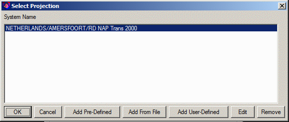 You can pick from this recently used
list, or pick the Add Pre-Defined to select from the built-in list.
You can pick from this recently used
list, or pick the Add Pre-Defined to select from the built-in list.
 The Add From File button reads in a projection saved to a file by
this routine or by SurvCE CSL or ESRI PRJ. The Edit button allows
you to change the name or parameters of a projection. The Remove
function removes a projection from the list of recently used
projections. The Add User-Defined routine defines a projection by
setting the ellipsoid, choosing the method and entering the
parameters. There are over 25 built-in ellipsoids to choose from
such as Clarke 1880. You can also manually enter the ellipsoid
values. The projection definition includes the 7 parameter Helmert
transformation to go from WGS-84 to the user datum. There are over
20 projection types to choose from such as Transverse Mercator.
After selecting the projection type, there are edit fields for each
of the parameters for the selected projection. The Test button
brings up a calculator to enter a lat/lon and report the projection
coordinates as a way to test that the projection parameters are
entered correctly and are working.
The Add From File button reads in a projection saved to a file by
this routine or by SurvCE CSL or ESRI PRJ. The Edit button allows
you to change the name or parameters of a projection. The Remove
function removes a projection from the list of recently used
projections. The Add User-Defined routine defines a projection by
setting the ellipsoid, choosing the method and entering the
parameters. There are over 25 built-in ellipsoids to choose from
such as Clarke 1880. You can also manually enter the ellipsoid
values. The projection definition includes the 7 parameter Helmert
transformation to go from WGS-84 to the user datum. There are over
20 projection types to choose from such as Transverse Mercator.
After selecting the projection type, there are edit fields for each
of the parameters for the selected projection. The Test button
brings up a calculator to enter a lat/lon and report the projection
coordinates as a way to test that the projection parameters are
entered correctly and are working. Besides Drawing Setup, these projection functions are also used in
the Coordinate Transformation function in Coordinate File
Utilities.
Besides Drawing Setup, these projection functions are also used in
the Coordinate Transformation function in Coordinate File
Utilities.
- Project Name and Job
Number are optional fields that are used in the header for
reports.
- Report Distance Scale
Factor is used to show distances in a second system besides
the drawing units. For example, this factor can be used to report
distances in meters when the drawing is in feet, or it can be used
to report grid distances when the drawings is in a ground
coordinate system. This factor is applied in commands that have an
option to label/report a second scaled distance such as the Inverse
command and Annotate Defaults that applies to the angle/distance
label routines. The scale factor can be entered directly into the
edit box or calculated using the Set button which has feet-meters
conversions as well as combined scale factor calculations for
grid-ground factors. See the Scale Points command for more
information on calculating the combined scale factor.
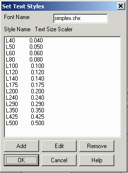
- The Set Text Styles button creates text styles in the
drawing for the current drawing Horizontal Scale with the specified
Font Name and list of Style Names and Text Size Scalers. For
example, when the Horizontal Scale is set to 50 and there is a
Style Name of L80 with Text Size Scaler of 0.08 in the list, then
this function will create a text style in the drawing called L80
with the text height of 4 (50 * 0.08).
- The Set Paper button allows you to draw a rectangle on
the screen that represents the edge of your paper. After you have
set the horizontal scale, press the Set Paper button and the Set
Paper dialog appears.
- The Layout option lets you specify landscape or portrait
paper orientation. Landscape layout is where the width of the page
is greater than the height of the page. Portrait layout is the
opposite.
- The Paper Size option allows
you to specify the paper size. The numbers in parenthesis represent
drawing units and will be multiplied by the horizontal scale to
determine the rectangle to be drawn. If you select the Other
option, you will be prompted on the command line for the horizontal
and vertical sizes of the paper.
Prompts (for Set Paper)
Pick or Type lower left corner point for border <(5000.00
5000.00 0.0)>: pick a point
Erase existing Set Paper boundary [<Yes>/No]? Y
This prompt only appears if there is an existing paper boundary in
this drawing.
Set Limits [Yes/<No>]? Y If you answer Yes to
Set Limits, drawing limits are enabled, and AutoCAD restricts the
coordinates you can enter to within the paper boundary. Drawing
limits also determines the area of the drawing that can display
grid dots, and the minimum area displayed by the Zoom All command
on the View menu. To turn drawing limits off, type in LIMITS on the
command line and set to Off.
Drawing Setup also sets the AutoCAD dimension scale (DIMSCALE)
and linetype scale (LTSCALE) to the Horizontal Scale.
Pulldown Menu Location: Settings
Keyboard Command: setup
Prerequisite: None
