Draw Field to Finish
This command turns data collector field notes into a final drawing by matching the descriptions of the field points with user-defined codes. The points are brought into the drawing with attributes defined by the code, including the layer, symbol, size and linetype. Draw Field to Finish also uses an improved coding method.
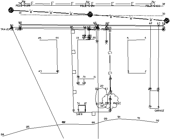 Example drawing results using the example points and
example code definitions
Example drawing results using the example points and
example code definitions
Two files are used in Draw Field to Finish - a coordinate file and a field code definition file. The coordinate file consists of point#, x,y,z points with text description fields. The description fields contain codes for the Draw Field to Finish processing. An ASCII data file can be converted into a coordinate file using the Import Text/ASCII File command. The field code definition file defines the layer, symbol, size and other actions to apply with each code. These file names are displayed at the top line of the Draw Field to Finish dialog box.
Draw Field to Finish can translate the field points into Carlson
points (also called coordinate geometry points or cogo points) with
a symbol, layer, and size defined by the code. The point settings
of whether to label the description, point number, and elevation
and whether to locate the point at zero or at the real Z can be
found in the Additional Draw Options of the Draw Field to Finish
dialog box. The Draw-Locate Points command has these point
settings stored separately in the Point Defaults menu.
Draw-Locate Points provides a simpler method for drawing
points compared with Draw Field to Finish.
Field-to-Finish will layerize the points and linework according
to the code definitions. If the layers to use are not already
defined, Field-to-Finish will create the necessary layers and
assign different colors. To have the same colors for these layers
in all your drawings, define the layers in the prototype drawing.
The prototype drawing is the default drawing that is loaded
whenever a new drawing is created. To define layers in the
prototype drawing, save your current drawing and then start a new
drawing with the New command. Don't give the new drawing a name,
just click OK. Then define the layers as desired with the
Layer command. When you are done creating layers, use the
Save As command and change to Drawing Template (.DWT) under Save as
Type. The default drawing template that is used is named
Carlson12.DWT. This template name will correspond to the version of
AutoCAD that is being used. You can overwrite this default template
or make a new drawing template. If you make a new one, you may want
to edit the Carlson icon to use the new one. To edit the icon,
highlight the icon with one click and then click the right mouse
button. Choose Properties and then Shortcut and change the drawing
template name.
There are two different methods for connecting linework. One
method creates line work by connecting points with the same code.
The linetype is defined by the code as either points only (no line
work), lines, 2D polylines, both 2D and 3D polylines, or 3D
polylines (breaklines). Distinct lines with the same code are
defined by adding a group number to the end of the code name in the
data file. With this method, all points with the description CODE1
will be one line while points with CODE2 will be another line. Both
CODE1 and CODE2 use the definition for CODE. For example, the code
EP could be a code for edge of pavement that is to be connected as
3D polylines. If there are two separate edge of pavement lines on
the left and right sides of a road, all the points for the left
side could have the description EP1 and the points on the right
side could be EP2. Besides having the number after the code, the
number can be used as a prefix by defining the code with a #
special character. For example, when the code is defined as #CODE,
then the points with descriptions 10CODE and 20CODE get matched to
this code.
The second method is the PointCAD format. This method also connects points with the same code. The difference is that instead of using a number after the code for distinct lines, you use the same code with an additional code for starting and ending the line. For example, +0 is used to start a line and -0 to end. So the coding for a segment of edge of pavement could be EP+0, EP, EP, EP-0. Another special code that has been added to Field to Finish is +7, -7. This 7 code will use the linetype definition of line, 2D polyline or 3D polyline defined by the Draw Field to Finish code. For example, if EP is defined as a 3D polyline, then the coding EP+7, EP, EP, EP-7 will create a 3D polyline. Otherwise codes like +0, -0, which is defined as start and end line, will draw EP as a line. Other PointCAD special codes are: +4 starts a curved 2D polyline, *4 starts a closed curved 2D polyline, +1 begins a 3-point arc, +5 starts a 3D polyline, *5 starts a closed 3D polyline, +6 starts a 2D polyline, *6 starts a closed 2D polyline, +7 starts a line whose type is specified by the field code definition, -05 starts a curved 3D polyline section, -50 ends that section, +8 starts a 2D and 3D polyline combination, *8 starts a closed 2D and 3D polyline combination, -08 starts a 2D and 3D polyline combination curved section, -80 ends that section. //, followed by a field code, concatenates that field code's description on to the point's description. For example, OAK//04 might become LIVE OAK TREE 4" if the field code OAK translates to LIVE OAK TREE and the field code 04 translates to 4".
The advantage to the PointCAD method is that you don't have to
keep track of line numbers. For example, if you are surveying 50
curb lines, the first method would require you to use 50 distinct
curb numbers. The advantage to the first method is that you don't
have to use the start and end codes. Also the Nearest Found
connection option applies to the first method.
Draw
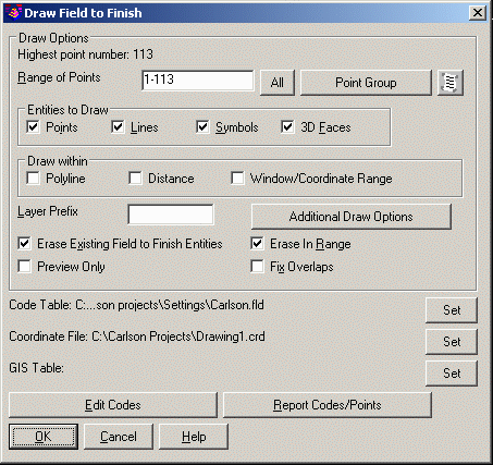
Range of
Points: Specify the
range of points to draw.
Point Group: Specify the point group(s) to process.
Entities To Draw: The Points option draws only the points and point attributes. The Lines option draws only the linework and the Symbols draws only the symbols. Any combination of these options can be processed as well as individual processing of each entity.
Draw
Within: These
options are methods to filter the points to draw. The Polyline
method prompts for a closed polyline and only draws points inside
this polyline. The Distance method uses a specified center point
and distance to only draw points within this circle. The
Window/Coordinate Range prompts for lower left and upper right
points to define the rectangular area to draw
points.
Layer Prefix: Optional layer prefix added to all entities drawn with Draw Field to Finish.
Erase Existing Draw Field to Finish Entities: When checked, this option will erase from the drawing any old entities created by previous Field-To-Finish runs before drawing the new entities.
Erase In Range: This option only erases and redraws those Draw Field to Finish entities that are within the specified range of points to process.
Preview
Only: When
checked, this option will temporarily draw the points and linework
and allow you to review it with zoom and pan.
Fix
Overlaps: This option checks the points drawn by
Field-to-Finish for any point labels that overlap with other points
or linework. For any overlaps, the point labels can be
automatically moved or you can step through each overlap to decide
how to handle it. See the command called Fix Point Attribute
Overlaps in the Points chapter for more information on this
feature.
Code
Table: Sets the FLD file to process which contains the code
definitions.
Coordinate
File: Sets the CRD file to process which contains the point
numbers, coordinates and descriptions.
GIS
Table: Sets the GIS file which defines the GIS feature and
attribute names. This file is optional and is used in GIS
processing.
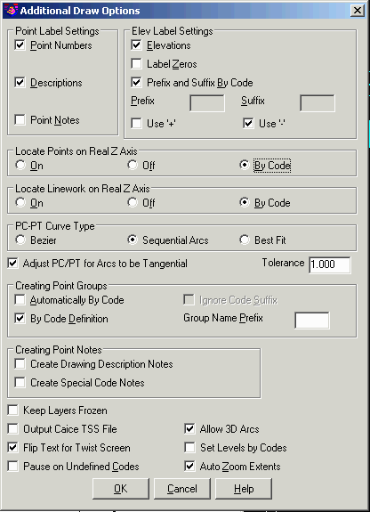
Additional
Draw Options
Point Label
Settings: Specify
whether you want Draw Field to Finish to label the Point Numbers,
Descriptions, or Points Notes which are contained in the note
(.NOT) file that is associated with the coordinate (.CRD) file. The
Attribute Labels option controls whether to draw GIS attribute
labels.
Elevation Label Settings: Specify the elevation labeling options. The Elevations toggle controls whether to draw the elevation attribute label for the points. The Label Zeros option will label the elevations of points with z=0. The Prefix and Suffix By Code sets whether to use the general Prefix and Suffix for all point elevation labels from this dialog or use the Prefix and Suffix defined in each code definition. Use '+' and Use '-' will place the appropriate symbol in front of the elevation. The Label In Inches option allows for elevation label in feet and inches instead of in decimals.
Locate Points on Real Z Axis: Choose between locating all the points at real Z elevation, all at zero elevation or to use the real Z setting as defined in the individual codes.
Locate Linework on Real Z Axis: Choose between drawing all the linework at real Z elevation, all at zero elevation or to use the 2D/3D polyline setting as defined in the individual codes.
PC-PT Curve
Type: Sets the
method for drawing curves with more than 3 points. The Bezier
option draws a smooth polyline through all the curve points. The
Sequential Arcs method draws multiple arcs with arc end points at
each of the curve points. These arcs are tangent to the preceding
line segment. The Best Fit method creates a single best-fit curve
for all the curve points between the PC and PT.
Adjust PC/PT
for Arcs to be Tangential: This option
will adjust the PC and PT polyline vertices to make the curve
tangential. The program will only adjust these points is the
adjustment distance is less than the specified tolerance. This
option applies to cases where the tangents are well defined and the
PC/PT are harder to survey exactly.
Creating Point Notes:
These options append point notes to the coordinate file data for
some of the data fields processed by Field-to-Finish. These notes
can then be used by other commands like List Points to report these
fields. For example, this enables List Points to report both the
point coordinate file description as well as the point drawing
description as generated by Field-to-Finish.
Keep Layers Frozen: This option will not thaw layers that
Field-to-Finish uses for drawing entities. So when you have this
option on and some layers are frozen, then you won't see the
entities that Field-to-Finish creates until you thaw those
layers.
Output Caice TSS File: This option creates a TSS file
from the processing results.
Flip Text for Twist
Screen: This option will rotate the point labels and symbol
by 180 degrees when needed to make them right-side up readable
relative to the current twist screen drawing view. This option
applies to the Rotate To Line and Rotate special code
(ROT).
Set
Levels By Codes: This option assigns the optional Level Names
for use by selection filters.
Auto Zoom Extents: When checked, this will force a zoom extents after Draw Field to Finish is done.
Pause on Undefined Codes: When checked, Draw Field to Finish will pause if it encounters a description that is not defined in the code table.
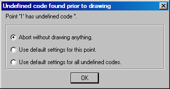
Abort without drawing anything: This stops the command. Run Draw Field to Finish again to correct the code table.
Use the default settings for this point: This option draws a point in the "MISC" layer with no linework. To set your own default, define a code called "SC_DFLT".
Use default settings for all undefined codes: This option will draw all undefined codes in the "MISC" layer by default or a user specified layer as defined in the "SC_DFLT" code. A good way to check the data file for unmatched descriptions is to use the Print Table command and choose the Data Points and Distinct Code options. This command will print the different codes in the data file and identify any undefined codes.
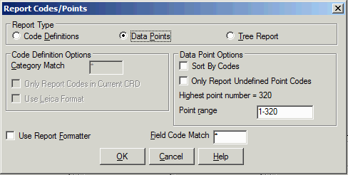
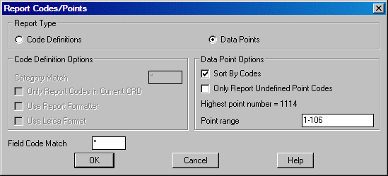
Report Codes/PointsThis routine prints the code table or the data file to the screen, file, or printer. A useful option here is to print the data file (CRD Points) and choose Sort by Codes which will group the data points by distinct codes.
 Edit Codes
The Field to
Finish dialog box allows you to load the coordinate and field code
definition files, view and edit the code definitions, view and edit
the coordinate file, view reports, and then return to the Draw
Field to Finish dialog box to process the files. The top section
displays the code definitions. The bottom section has three columns
of functions each pertaining to controls for different elements of
the command. The Code Table section provides controls for
settings, sorting and reporting of codes. The Code
Definitions section provides tools for the creation and editing
of codes. The Feature Settings section provides controls for
the special tree and pipe feature types.

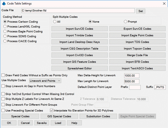
Code Table
Code Table Settings: These options provide tools for defining the coding method to be used for processing of the point data. Various import tools allow for the importing of codes from different software packages. Controls for handling multiple codes are located on this dialog. All special codes can be replaced to other characters defined by the user. The special codes are listed and edited on this dialog.
 Set:
Choose this
button to specify a new code table. The name of the current table
is shown in the field to the right of this button.
Set:
Choose this
button to specify a new code table. The name of the current table
is shown in the field to the right of this button.
Coding
Method
Carlson Coding: When
checked, this option interprets and processes coordinate files
based upon the Carlson Coding method and data collection
method.
Eagle Point Coding: When checked, coordinate files are processed based on the Eagle Point Data Collection method. When selected the Eagle Point Codes button becomes available for selection and displays the following dialog. This dialog allows for customization of the eagle point special designators.
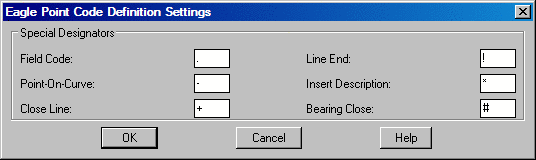
Currently the supported designators include, "Field Code", "Point-On-Curve", "Close Line", "Line End", "Insert Description" and "Bearing Close". Also supported is the ability to recognize overwriting of descriptions just as Eagle Point does by using the space separator instead of the "Insert Description" designator. Examples of supported coding are as follows:
.TC
Places a
node and or line per the field code library.
TC Places a node and or line per the field code
library.
-TC Specifies a point on a curve.
TC- Specifies a point on a curve.
..TC Stops the line.
TC! Stops the line.
.TC+ Closes the line back to the starting point.
TC+ Closes the line back to the starting point.
.TC# Typically coded on the third corner of a
rectangle to close the figure with having to locate the fourth
corner.
TC# Typically coded on the third corner of a
rectangle to close the figure with having to locate the fourth
corner.
WV.W1 Places a node as specified by the code "WV" in
the field code library and then begins a line as specified by code
"W" in the field code library.
.TC.EP.FL Results in three lines coming together.
TC1.TC2.TC3 Results in three lines coming together.
All three lines are specified by the definition of the single code
"TC" in the field code library.
TC.TC1 When used in conjunction with the "Draw Field
Codes Without a Suffix as Points Only" toggle, "TC" will be
recognized as the node and "TC1" will be recognized as the line so
that if the code "TC" in the field code library is defined as a
polyline, line or 3D polyline, duplicate lines will not be
unintentionally placed when this shot only pertains to a single
element. Keep in mind that all line work must have a numeric suffix
when using this toggle.
TREE * OAK Result on screen would be: TREE OAK
TREE OAK * Result on screen would be: OAK TREE
TREE OAK Result on screen would be: OAK
TC1!.TC2-.VLT6# Stops "TC1", continues "TC2" as a
point on a curve and closes VLT6 as a rectangle using the "Bearing
Close" code.
Note: The use of the "Use Multiple Codes for Linework Only" toggle is recommended when using Eagle Point Coding.
CAiCE
Coding: When
checked, coordinate files are processed based on the CAiCE Data
Collection method. Examples of supported coding are as follows:
169 is just the code 169.
145C10 is the code 145 and line #10.
169C25C is the code 169, line #25, and the
point is on a curve.
172C12B is the code 172, line #12, and this point
closes the line.
SDMS
Coding: This option
processes coordinate files based upon SDMS coding method. When
active, the program will prompt for an SDMS .PRJ file to
process.
LandXML
Coding: This method prompts for a LandXML or Leica/Hexagon
HeXML file to use with the processing. This method applies when the
point descriptions do not have linework coding and the LandXML file
has PlanFeatures that define how points are connected to create
linework. This method reads the LandXML file to find the points
that begin and end lines and curves.
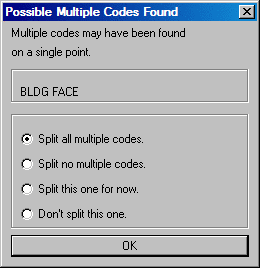
Split Multiple Codes: Multiple codes are defined by including each code in the point description field separated by a space. A single data point can be used in different lines by assigning it multiple codes. For instance, a point might be part of both a curb line and a driveway line with a description of "CURB DRW". Field-to-Finish uses spaces as the delimiter for multiple codes. You should avoid spaces in the descriptions except for where multiple codes are intended or after the "/" character. For example, a code for light post should not be "LGT POST" but instead should be "LGTPOST".
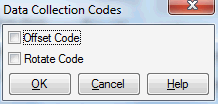
There are three options for the handling of multiple codes when encountered. The All option will split all multiple codes and process each code based upon their code definition. When None is select both codes will be processed based upon their code definition. If the Prompt option is checked on, when Field-to-Finish detects multiple codes on a point the following dialog will be displayed with options for handling the codes.
Import Land Desktop Desc Key: This option imports and converts a Land Desktop Description Key into a Carlson Draw Field to Finish (fld) code definition file. The Land Desktop Description Key file is a mdb file and is found in the Land Desktop Project file path. It is located in the under the COGO/DescKey directory.
Import TDS
Codes: This option
imports TDS codes into the Carlson Field to Finish (fld) code
definition file.
Import
Topcon Codes: This function imports Topcon codes and layers
from an XML file.
Import Trimble Codes: This option imports Trimble .FXL file codes into the Carlson Field to Finish (fld) code definition file.
Import Civil 3D Codes: This option imports Civil 3D .fdb_xdef file codes into the Carlson Field to Finish (fld) code definition file.
Import Eagle Point Codes: This option imports Eagle Point codes into the Carlson Field to Finish (fld) code definition file.
Import EFB: This option imports the SDMS Electronic Field Book codes (.xml) into the Carlson Field to Finish (fld) code definition file.
Import C&G Description Table: This option imports C&G code tables (tbl) into the Carlson Field to Finish (fld) code definition file.
Import Text/ASCII Codes: This option imports code definitions from a user-defined format. Each row in the text file should represent one code. The program will prompt for the delimiter (ie. comma separated) that is used in the text file and then for the field type for each of the columns (ie. "Layer" or "Description").
Import GIS Feature Codes: This option imports features in a .GIS file from Define GIS Features into F2F codes.
Import SurvCE Codes: This option imports a SurvCE Feature Code List (fcl) into a Carlson Field to Finish (fld) code definition file.
Export
SurvCE Codes: This option
creates a SurvCE Feature Code List (fcl) from the current a Carlson
Field to Finish (fld) code definition file.
Merge Code
File: This
function adds code definitions from another (fld) code definition
file into the current code table. The program shows a list of the
codes from the other file that are different than the current code
table. You can choose which codes to import. Any codes that
conflict with an existing code definition are defaulted to not
import.
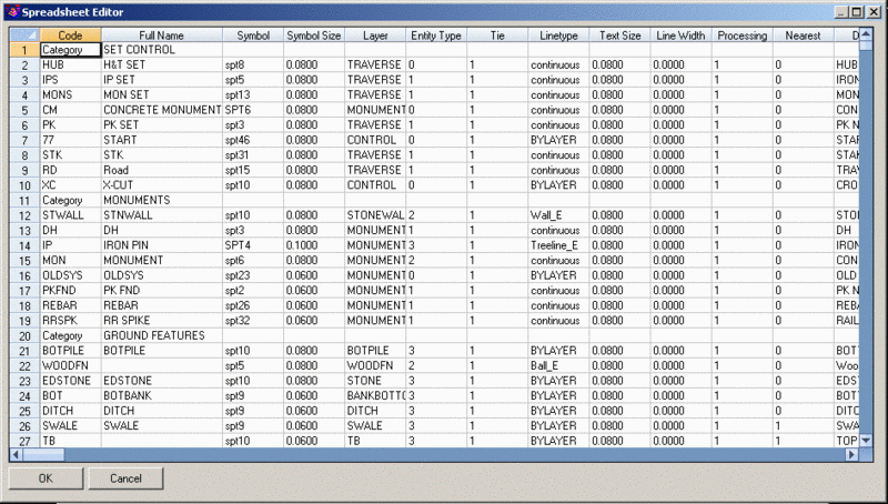
Spreadsheet
Editor: This
function lets you edit all the codes with all their settings in a
single large spreadsheet. This method can be a handy way to use
copy and paste to edit the codes. This method can also be quicker
to make many changes than navigating the Edit Code dialog. This
method is for expert users and you need to take care make valid
inputs.
Draw Field Codes Without a Suffix as Points Only: This option is useful for when wanting to use a field code sometimes for linework and sometimes for just points but it is preferred to number the lines rather than using start and stop codes. For example, if the field code EP is defined to use the Line Entity type, then EP25 will be drawn as a Line, however if just EP is used, no linework will connect to that COGO point.
Use Multiple Codes: When multiple codes are detected for a point, this setting controls how to draw the additional codes. The Linework and Points setting fully draws the multiple codes. The Linework Only method uses the multiple codes for drawing linework and only draws a point based on the primary code. If you want symbols for all multiple codes, then choose the Linework and Symbols option.
Max Delta-Height for Linework: Use this option to specify the maximum elevation difference that Draw Field to Finish should draw any section of linework. This option is for use with 3d polylines and lines.
Max Length
for Linework: Specify the
maximum length that Draw Field to Finish should draw any section of
linework.
Skip 1st/2nd
Symbol Control When Missing 3rd Control: For
multi-point symbols when the 3rd control point is missing, this
option centers the symbol on the 1st point instead of using the 1st
point as a control point.
Use MText
for Linework Descriptions: Controls whether to create MText or
regular Text entities for linework description labels.
Skip
Multiple Z Labels For Linework At Same Z: This option labels
only the first point elevation for points on polyline or rectangle
from the RECT code when the elevation difference between the points
is less than the specified Z Tolerance and the horizontal
distance is less than the Distance Tolerance. For example,
for points on the corners of a level utility pad, this option will
label the pad elevation just once.
Stop
Linework At Gap In Point Numbers: This option is a method for
controlling the start and stop of drawing linework. This method
will automatically stop linework where there is a gap in the point
numbers for the linework code. For example, if there are points
with code EP then points with code CL then more points with code
EP, the EP linework for the first set of EP points will stop at the
last EP before the CL points and then new EP linework will start
after the CL points.
Stop
Linework For Different Point Groups: This option applies to
when you have points for the same job collected at different times
or with different crews and you want to prevent linework connecting
points between them. For example, this applies when you survey a
job with two crews and combine their points into a single CRD and
both crews used "EP1". In this case, to keep each set of "EP1"
separate, you can put each set of points into a separate point
group with Point Group Manager and use this Field-to-Finish option.
The Point Group Filter is optional and is used to make the
program only check groups that match the filter. A point can be in
multiple groups such as “CONTROL” and “DAY1”. Some groups could be
used for different days such as “CONTROL”. So the Point Group
Filter could be set to “DAY” to filter out the common groups and
only process the time related groups.
Default
Distinct Point Layer: These settings control the default layer
for when the Distinct Point Layer option is turned on for each code
definition.
Use
Preceding Special Codes: This setting tells the program to
expect the special codes before the main code. For example, if
"BEG" is the special code for begin linework and "EP" is a main
code, then the program looks for "BEG EP". The default sequence is
for the special code to come after the main code as in "EP
BEG".
Interpolate
No Elevation Points for 3D Polyline: For points tagged as "No
Elevation" that are part of a 3D polyline, this option will
interpolate an elevation for this point from the other points in
the 3D polyline. Otherwise, this point will be skipped in the 3D
polyline.
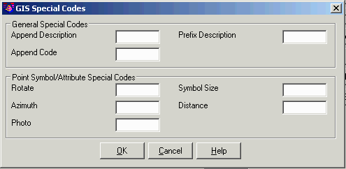
GIS Special
Codes: This option
allows you to use GIS attribute for Field-to-Finish special coding.
For a select group of special codes, a GIS attribute can be
assigned. When processing the points, if a point has GIS data for
the specified attribute, then that attribute value is used for the
special coding. For example, you can have a GIS attribute of
COMMENT set to the Append Description special code. Then if a point
has a GIS attribute for COMMENT, the value of that COMMENT will be
added to the description label for that point.
The Append
Code option adds the GIS code to the description code to make the
code for processing. For example, for a point with description
"ROAD" and a GIS attribute named "TYPE" with a value of "DIRT",
then set the GIS Special Code for Append Code to "TYPE" and the
program will process this point using the combined code of
"ROADDIRT".
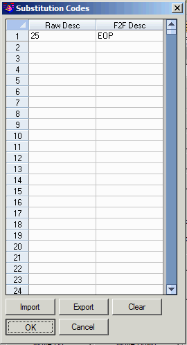
 Substitution
Codes: This option
defines a lookup table for translations of the raw point
descriptions. This translation is done as a pre-processing step
before the regular Field-to-Finish processing. For example, if you
had a substitution setup for "25" = "EOP", then a point
description of "25" would get translated to "EOP" and then this
"EOP" would be processed with Field-to-Finish. Use the Import and
Export functions to load and save substitution codes to a comma
separated text file. The Match With Number Suffix option will match
with a number following the string. For example, "CL" will match
with "CL2". Otherwise, the strings have to be an exact match. The
substitution codes are stored in a file named f2f_sub.dta in the
%appdata%\Carlson...\USER folder.
Substitution
Codes: This option
defines a lookup table for translations of the raw point
descriptions. This translation is done as a pre-processing step
before the regular Field-to-Finish processing. For example, if you
had a substitution setup for "25" = "EOP", then a point
description of "25" would get translated to "EOP" and then this
"EOP" would be processed with Field-to-Finish. Use the Import and
Export functions to load and save substitution codes to a comma
separated text file. The Match With Number Suffix option will match
with a number following the string. For example, "CL" will match
with "CL2". Otherwise, the strings have to be an exact match. The
substitution codes are stored in a file named f2f_sub.dta in the
%appdata%\Carlson...\USER folder.
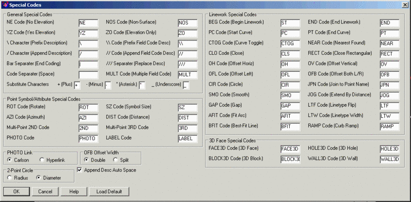
 Special
Codes: This section
allows you to substitute the existing predefined special codes and
characters with your own. Draw Field to Finish recognizes several
special codes. A special code is placed before or after the regular
code with a space separating the code and special code. The Append
Desc Auto Space option applies to the special codes that control
the point description label. This option sets whether to insert a
space in the description label when appending to the
description.
Special
Codes: This section
allows you to substitute the existing predefined special codes and
characters with your own. Draw Field to Finish recognizes several
special codes. A special code is placed before or after the regular
code with a space separating the code and special code. The Append
Desc Auto Space option applies to the special codes that control
the point description label. This option sets whether to insert a
space in the description label when appending to the
description.
Here is a listing of the default special codes and characters.
Special Characters
The characters (*, -, +, /, and _) can be used and substituted in Draw Field to Finish. The way these characters are used is that when the file is processed the description field is searched for these characters. If the "+" symbol was changed to "-" then the program would look for "-" and change it to "+". This is useful when a particular data collector may not have all the symbols available. With these substitutions you can make a character that is provided on the data collector generate the symbol needed. Multiple characters can also be used. For example "--" can be used to in order to produce a "/" character or any of the characters listed above.
Special Codes
"/": Append Description
Carlson points in the drawing have point attributes including a
description. When Field-to-Finish draws the points, the point
description from the coordinate file is processed to match a code.
The code then defines the description that is drawn with the point.
For example, consider a code of "UP" with a description of "POLE"
and a data point with the description "UP". The data point
description "UP" would be matched with the code "UP" and the point
would end up being drawn with the description "POLE". A special
character "/" (the forward slash or divide key) can be used for an
unprocessed description to append. Everything after the "/" is
added directly to the point description and is not considered a
code and no further substitution is done on it. For example, a data
point with the description "UP / 150" with the same code "UP"
definition above would be drawn with the description "POLE
150".
"///":
Replace Description
This special code takes the part of the description after the "///"
and uses it as the point description label.
"\": Prefix
Description
This special code takes the part of the
description after the "\" and puts it as the prefix before the
point description. For example, a data point with the description
"TR \ 24ft" and a "TR" code definition with a description of "Tree"
would be drawn with a description of "24ft Tree".
"//": Append Field Code Description
This special code causes text after the "//" to be interpreted as a field code. That field code's description is then appended to the first field code's description. For example, if the field code 02 has the description 2" and the field code OAK has the description oak tree, then 02//OAK will result in the point having the description of 2" oak tree. If the "/" character has been replaced with a different character, for example with a & character, then the "//" code would become "&&".
"\\": Prefix Field Code Description
This special code is the same as "//" except that field code's
description is then prefixed instead of appended to the first field
code's description.
"|": End Coding
The bar separator indicates the end of coding. Everything after the bar is ignored for Field-to-Finish processing.
MULT: Multiple Field Code
This code applies when the Split Multiple Codes under Code Table Settings is set to None and you want to override this setting and explicitly spilt selected codes. Multiple codes apply to points with dual code definitions for drawing two different style points or for connecting different linework to the same point. For example, if a point is both a sidewalk and driveway corner, then the point description could be "SW MULTDR".
PC: Start Curve
This code begins a three point arc or a curved line when used with the "PT" code (see below). The point with this special code is the first point on the arc. The next point with the code is considered a point on the arc, and third point with the code is the arc endpoint. For example (in point number, X, Y, Z, description format),
10, 500, 500, 0, EP PC - start curve
11, 525, 527, 0, EP - second point on curve
12, 531, 533, 0, EP - end point of curve
PT: End Curve
This code can be used with "PC" to define a curve with more than three points or a tangent two-point curve. Starting at the point with the "PC", the program will look for a "PT". If the "PT" is found, all the points between the "PC" and "PT" are used for the curve which is drawn as a smoothed polyline that passes through all points and only curves the polyline between points. If no "PT" is found, then the regular three point arc is applied as explained above. If no points are found between the "PC" and "PT", then the point prior to the "PC" and the point after the "PT" are used to create tangents for the resulting curve.
AFIT: Fit
Arc
This special code adjusts the PC/PT points for the current arc
to make the arc tangential. This special code is a way to
individually control this tangential arc adjustment. To adjust all
arcs within a specified adjustment tolerance, use the Adjust PC/PT
setting under the Additional Draw Options from the first
Field-To-Finish dialog.
BFIT: Best-Fit Line
This code creates a best-fit line using the points for the
linework. This feature can be used when you have multiple points on
a feature that you know is a straight line such as a sidewalk and
you want a single line to be drawn. Each of the points that you
want to include in the best-fit need to have the BFIT code.
CTOG: Curve Toggle
This special code toggles curve mode on and off. Instead of using PC to start a curve, you can use CTOG. Likewise, instead of using PT to end a curve, you can use CTOG.
CLO: Close
This code forces the lines drawn between a series of points with the same code to close back to the first point with the same code. For example, shots 1-4 all have the BLD description with the exception of point 4. Its description is BLD CLO. This will force the linework drawn for the BLD code to close back to point 1 which is the first point with the description of BLD.
GAP
This special code makes a single segment break in the current linework. For example, if you have a curb polyline that you want to break to skip over a driveway, then you could add the GAP code at the start of the driveway and continue the curb as normal on the other side.
NE: No Elevation
This code represents no elevation. A point with this special code is located at zero elevation.
YZ: Yes Elevation
This special code locates at the point entities at the coordinate elevation and overrides any other setting for locating the point at zero elevation.
NOS: Non-Surface
This code indicates that the point should be "non-surface"; that is, that it should be ignored when contouring or creating surfaces. This can also be controlled per-field code by turning on the Non-Surface toggle in the Edit Field Code Definition dialog box.
ZO:
Elevation Only
This code represents elevation only (Z-Only). A point with this special code is used at part of a 3D polyline for elevating the 3D polyline without effecting the horizontal position of the polyline. For example, this code could be used on a grade break point along a cube where only the elevation should change and not the horizontal alignment.
PHOTO
This code attaches a photo file to the point. The name of the
photo file should be right after the PHOTO code. The PHOTO Link
setting controls whether the photo is attached using a
Carlson-format link or a CAD Hyperlink. Use the Image Inspector
command to view photos attached to points by either link method. To
use the Hyperlink, you can Ctrl-click or right-click on the point
entity.
In addition to the PHOTO code, Field-to-Finish will also
automatically create the photo links for SurvCE photos. The program
looks for the photo database from SurvCE which should have the same
name as the coordinate file with an extension of .phdb. This photo
database file should be in a sub-folder of the coordinate file
folder and called Pictures_X where X is the name of the coordinate
file. For example, if your coordinate file is
C:\Projects\Job1\Job1.crd, then the program looks for
C:\Projects\Job1\Pictures_Job1\Job1.phdb.
When SurvCE stores photos, it creates this photo database using
this naming. So to process with Field-to-Finish, copy the
coordinate file and photo files from the data collector to your
computer.
LABEL
This code controls the point attribute format using a
number after the code. This number uses 0=attribute block, 1=text,
2=both, 3=none. For example, LABEL1 means draw that point using
text attributes.
COLOR
This code sets the entity color. The color is specified
after the "COLOR" code by either a CAD color number (1 to 256) or
color letter. The color letters are R=red, Y=yellow, G=green,
C=cyan, B=blue, M=magenta, W=white. For example, COLOR1 means use
CAD color 1 (red) and COLORB means use color blue.
Offsets: OH, OV, OFL, OFB
The codes "OH" and "OV" stand for offset horizontal and offset vertical. These offset codes apply to 2D and 3D polylines. A single set of offset codes can be used to offset the polyline a set amount. For example,
10, 500, 500, 100, EP OH2.5 OV-.5
11, 525, 527, 101, EP
12, 531, 533, 103, EP
This would create a polyline connecting points 10,11 and 12 and an offset polyline with a 2.5 horizontal and -0.5 vertical offset. The direction of the horizontal offset is determined by the direction of the polyline. A positive horizontal offset goes right from the polyline direction and a negative goes left. The horizontal and vertical offset amounts apply starting at the point with the offset codes until a new offset code or the end of the polyline. Only one horizontal and vertical offset can be applied to 2D polylines. For 3D polylines, multiple offset codes can be used to make a variable offset. For example,
10, 500, 500, 100, EP OH2.5 OV-.5
11, 525, 527, 101, EP OH5.5 OV-.75
12, 531, 533, 103, EP OH7.5
This would offset the first point horizontal 2.5 and vertical -0.5, the second point horizontal 5.5 and vertical -0.75 and the third point horizontal 7.5 and vertical -0.75.
When there are multiple "OH" codes for the same point, the polyline is offset multiple times.The "OFL" code stands for offset left horizontal. The only difference with the "OH" code is that you don't have to enter the "-" to go left.
The "OFB" code stands for offset both left and right horizontal. For example, if the points follow the center of a ROW, the OFB code can be used to create the left and right edges of the ROW. There is a setting in Special Codes for Offset Both for whether the offset value if for the full or half width between the two offset lines. Also, there is a setting in each code definition under the Linetype tab for whether to create a closed polyline from the left and right offset polylines.
SZ: Symbol Size
This code is used to set a different symbol size. There are several ways to use this code. It can take multiple scale factors for different dimensions by putting an ID character after the factor.
SZ: If nothing follows the SZ code, then the next point with the same field code as the current point will be used to determine the size.
SZ#: The value of the new symbol size is specified after the SZ. This value is the actual size in drawing units. For example, SZ2.
SZ#X: The value after the SZ is used to scale the symbol in the X dimension. For example, SZ2X.
SZ#Y: The value after the SZ is used to scale the symbol in the Y dimension. For example, SZ2Y.
SZ#Z or SZ#V: The value after the SZ is used to scale the symbol in the Z (Vertical) dimension. For example, SZ2Z.
SZ#H: The value after the SZ is used to scale the symbol in the X,Y (Horizontal) dimensions. For example, SZ2H.
SZ#S: The value after the SZ is a symbol size scaler that get multiplied by the drawing horizontal scale to determine the actual drawing units. For example, SZ0.2S.
The X, Y, Z, V and H can be combined. For example, to scale a symbol by 10 horizontally and 25 vertically, use SZ10H25Z. Or to scale a symbol by 2 in the X direction and 4 in the Y direction, use SZ2X4Y.
When multiple SZ codes are used in the same point description, the symbol is drawn multiple times at the different sizes. For example, a point description of "TREE SZ5 SZ10" will draw the tree symbol twice. One symbol will be size 5 and the other size 10.
ROT: Rotate
This code is used to set the rotation of the point symbol. If a point number follows the ROT code, then angle from the current point to this point number is used for the rotation. For example, "ROT45" would rotate the symbol towards point number 45. If there is no point number after the ROT code, then the rotation point is the next point number with the same code as the current point or a companion code for the current code. ROT can also be used to rotate towards an angle clockwise from north by using `+' or `-' in front of the number. For example ROT+45 rotates the point symbol to the northeast and ROT-90 rotates the point symbol to the west.
SMO: Smooth
This code is used to smooth the polyline.
AZI & DIST
The AZI and DIST codes are used together to offset the point. The AZI sets the offset azimuth and DIST sets the distance. The values should directly follow the code. For example, AZI25 DIST4.2 would draw the point offset 4.2 at an azimuth of 25 degrees.
JOG: Extend By Distance
The "JOG" special code allows for additional points to be inserted into the line work at perpendicular or straight offsets. Only offsets should follow the JOG code. Positive numbers indicate a jog to the right and negative numbers indicate a jog to the left. Alternatively, "R#" and "L#" can be used where # is the distance to either the right or the left. Finally, "S#" can be used to make an offset straight ahead by using a positive # or behind by using a negative #. For example, "BLDG JOG S10.1 R5 L12.2 L5 L12.2" or equivalently "BLDG JOG S10.1 5 -12.2 -5 -12.2" advances 10.1 units and then draws a closed rectangle on the right hand side of an existing line. The offsets are always done in the X-Y plane. If the current line is vertical, an offset to the right is along the positive X-axis.
JPN: Join to Point Name
The "JPN" (Join to Point Name) special code joins to the point named immediately after the code. For example, "JPN205" causes a line to be drawn from the current point to the point "205". JPN is designed to work for adding a segment at the start of linework. So the point with the JPN code should be at first segment of the linework.
XSCT: Template
This special code defines a template from a series of points with this special code. This template is then applied like a template defined under Linetype for a code. This XSCT code is a way to define a template in the field instead of having a template with fixed dimensions defined in the code table. For example, you could have a code for BC for back-of-curb. Then store three points with a description of "BC XSCT" for three points to cross section the curb: back-of-curb, top-of-curb and flow line. After these three "BC XSCT" points, you could have single "BC" points along the curb and the program will apply the template along these curb points and draw three parallel lines.
NEAR: Nearest Found
This special code sets the current polyline to Nearest Found connection order. This applies to codes that have the Connection Order set to Sequential and you want to override this setting to Nearest Found for the current polyline.
RECT: Close Rectangular
The "RECT" special code creates a rectangle as a 2D or 3D polyline using one of two different methods. If a number follows "RECT" (e.g., "RECT10"), a rectangle will be drawn 10 units to the right of the last two points ending on the point with the "RECT" code. Use a negative offset to place the rectangle on the left side (e.g., "RECT-2.5"). For example if locating the left side of a 10' rectangular concrete pad using the code conc for concrete, the description of the two left points would be (conc) for the first point and (conc rect10) for the second. If no number follows "RECT", then the polyline will be closed by shooting right angles from the first point of the polyline and the current point and creating a new point where those two lines cross. This method requires three points be established on the rectangle. In this method, the "RECT" code can be on any of the polyline points.
LTF: Lintype Flip
This special code switches the side for the linetype. This option applies to non-symmetrical linetypes like the treeline or guard rail for when you want the linetype to face the other way.
LTW: Line Width
This special code sets the line width. The width value is entered after the LTW code. This width is applied to lines and 2D polylines.
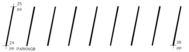
PARKING: Parking
This special code draws parking stall lines using three points. Points one and two are used to draw the first parking line and define the length and angle of the lines. The thrid point defines that position of the last parking line. A number needs to follow the PARKING code for the number of parking lines to draw. For example, PARKING8.
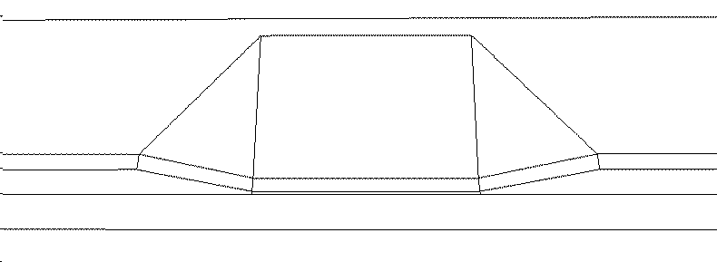
RAMP: Curb Ramp
This special code adjusts the 3D polylines to create a curb ramp. The routine looks for parallel 3D polylines for the bottom of curb, top of curb and back of curb. These 3D polylines can be created in Field-To-Finish by using a Template under the Code > Linetype definition, or using the offset special codes, or by having three separate 3D polylines. The ramp is centered at the point with the RAMP code. The dimensions of the ramp follow the code in order of width, depth and taper. For example, a description of "BC RAMP 3 2 1" uses "BC" for a bottom of curb code then "RAMP" for the special code and 3 for the width, 2 for the depth and 1 for the side taper.
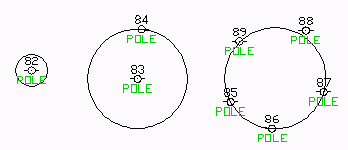
CIR: Circle
The "CIR" special code causes the point to create a circle in one of three different ways. The first way uses just the current point as the center with the CIR special code followed immediately by the radius. For example "CIR7.5" will create a circle centered on this point with radius 7.5 and at the elevation of the current point. The second method uses two points, the first point specifying the center and the elevation, and the second point specifying the radius. Only the first point has the "CIR" special code and the second point is the next point with a matching field code. Another variation of method 2 is using 2 points that are on the perimeter and define the diameter. For the 2 point method, whether the points define the radius or diameter is defined on the Code Table Settings > Special Codes dialog. The third method uses 3 or more points that specify the perimeter of the circle in 2D with the first point specifying the elevation. For this method, the "CIR" special code is only on the first point and the rest of the points are the next points with matching field codes.
The "CIR" code can be used with all of the linetypes including "points only". The circles are always parallel to the X-Y plane unless the code linetype is set to "3D Polyline". Then the circle is drawn as a 3D polyline. Any active linework for the code is ended before processing the "CIR" special code.
PointNo. Description
Method 1 (Single point at center with radius value)
82 PP CIR7.5
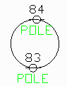
Method 2a (Point at center plus point at perimeter)
83 PP CIR
84 PP
Method 2b (2 Points on perimeter that define the diameter)
83 PP CIR
84 PP
Method 3 (Points on perimeter)
85 PP CIR
86 PP
87 PP
88 PP
89 PP
Method 2b
When used on the first point of a multi-point symbol, the "2ND" code indicates that the second point of the sequence (i.e., the next point after the current one) should be used as the second symbol insertion point for a multi-point symbol. Please refer to Symbol Pts in the Edit Field Code Definition section below.
3RD: Multi-Point Code
When used on the first point of a multi-point symbol, the "3RD" code indicates that the third point of the sequence should be used as the third symbol insertion point. The "3RD" code should be used with the "2ND" code. Please refer to Symbol Pts in the Edit Field Code Definition section below.
3D Special Codes
Below are the special codes that can be used for the easy creation of 3D surfaces. The resulting 3D face entities can be viewed in the Carlson 3D viewer by entering "cube" on the command line.
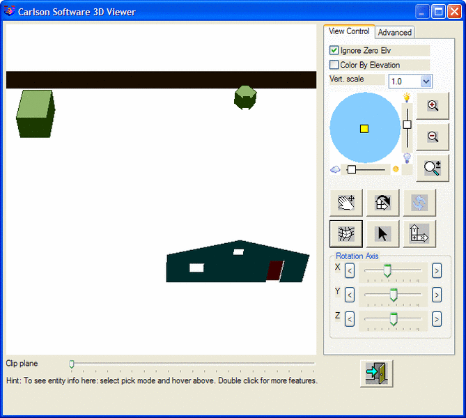
FACE3D
Makes a triangle mesh of 3D face
entities by triangulating points starting with the current point
and continuing until the line ends or another 3D special code is
found. The points must be ordered along the perimeter. Although the
mesh will be built if the points are clockwise or counterclockwise
along the perimeter, the visible side in the Carlson 3D viewer,
"cube", is the clockwise side by default. On the Advanced tab, the
shading mode may be set to Shade both or Shade back
if you would prefer to see both sides or just the counter-clockwise
side.
HOLE3D
Makes an exclusion area within the triangle mesh identified by the point number following this code (e.g., “HOLE3D101” will start a hole in point # 101). If no point number is given (“HOLE3D”), the exclusion area is applied to the last mesh or if there is a mesh in the process of being constructed by the current sequence of points, it is ended and the hole is applied to it. Note that a hole can only be applied to a mesh that was created by FACE3D (not BLOCK3D or WALL3D). Note also that it can be difficult to predict what the “last mesh” was if it used a different field code since the points of the coordinate file are processed by order of field code first and then point number. There is no limit to how many holes can be applied to a FACE3D mesh. The points of the hole itself are not added to the FACE3D mesh; they are projected on to the best plane that contains the FACE3D mesh and then the hole is cut-out.
Example
1:
2500 HOUSE1 FACE3D /front of
house
2501 HOUSE1
2502 HOUSE1
2503 HOUSE1
2504 HOUSE1
2505 VENT1 HOLE3D2500 /applies
2505-2508 as a hole to last mesh that uses point #2500. So any
point in the range 2500-2504 would have the same
effect.
2506 VENT1
2507 VENT1
2508 VENT1
Example 2:
2500 HOUSE1 FACE3D /front of
house
2501 HOUSE1
2502 HOUSE1
2503 HOUSE1
2504 HOUSE1
2505 HOUSE1 HOLE3D /stops the
above mesh and applies 2505-2508 as a hole
2506 HOUSE1
2507 HOUSE1
2508 HOUSE1
Example 3:
2500 HOUSE1 FACE3D /front of
house
2501 HOUSE1
2502 HOUSE1
2503 HOUSE1
2504 HOUSE1
2505 WINDOW1 FACE3D HOLE3D2503 /applies
2505-2508 as a hole to above mesh 2500-2504 and starts a new mesh
using the WINDOW field code.
2506 WINDOW1
2507 WINDOW1
2508 WINDOW1
Example 4 (same result as Example 3):
2500 HOUSE1 FACE3D /front of
house
2501 HOUSE1
2502 HOUSE1
2503 HOUSE1
2504 HOUSE1
2505 WINDOW1 FACE3D /starts a
new mesh using the WINDOW field code.
2506 WINDOW1
2507 WINDOW1
2508 WINDOW1 HOLE3D2504 /makes the
mesh 2505-2508 also be a hole in the mesh
2500-2504.
BLOCK3D
WALL3D
Makes a set of 3D faces above the polyline using a height value entered after the code (e.g., “WALL3D2.3” with height 2.3). This height is a signed value so you can shoot either the top of the wall or the bottom of the wall. The height can be negative if the points on the top of the wall have been shot. If no height parameter exists, then the height is determined by the distance from the current point to the next point.After the height value, you can have a width/thickness value. If no width value is entered, then a width of zero is used. When the width value starts with a minus "-", then the width is put on the left side of the points. When the width value starts with a plus "+", then the width is put on the right side of the points. When the width value has no plus or minus, then the points go through the center of the wall width.
Both sides of the wall will have triangles and so both sides will always be visible in the Carlson 3D viewer.
Example -- 6' high wall shot along the bottom:
2000 1000.000
1060.000 100.000 WALL1 WALL3D6.0 /wall
6'
2001 1100.000
1060.000 100.000 WALL1
2002 1100.000
1160.000 100.000 WALL1
Example -- 6' high and 1.5' wide wall shot along the bottom:
2000 1000.000
1060.000 100.000 WALL1 WALL3D6.0 1.5 /wall 6'
high and 1.5' thick
2001 1100.000
1060.000 100.000 WALL1
2002 1100.000
1160.000 100.000 WALL1
Example -- 6' high wall, height specified by 1st to 2nd point, shot along the bottom:
2020 1100.000
1160.000 100.000 WALL2 WALL3D /height by 2nd
pt
2021 1100.000
1160.000 106.000 WALL2
2022 1000.000
1160.000 106.000 WALL2
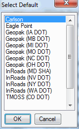
Load Default
This button sets the special codes to Carlson, Eagle Point, Geopak,
InRoads or TMOSS defaults.
 Code Table
(continued)
Code Table
(continued)
Sort Table - This sorts the code table by either code name or layer.
Report Codes/Points - This routine prints the code table or the data file to the screen, file, or printer. A useful option here is to print the data file (CRD Points) and choose Sort by Codes which will group the data points by distinct codes.
Code Table by CRD - This command will create code table definitions based on the coordinate file field descriptions. This is useful when creating a code table from scratch.
Save: Saves the Draw Field to Finish field code definition (.FLD) file.
Save As: Reacts the same as Save but allows for specification of file name and location to save to.
Code Definitions
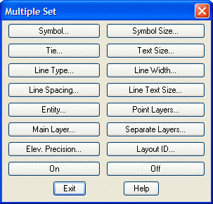
Edit:
If only one field code is selected, then this command opens the
Edit Field Code Definition dialog box. If multiple field codes are
selected (by holding down the control key or shift key and clicking
on the rows), then the Multiple Set dialog box will
open.
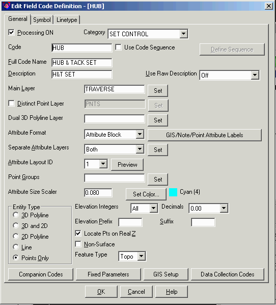
Processing ON: This toggle controls whether this code will be processed.
Code: This is the key name that identities the code and is matched with the field data descriptions. It is important to note that the * character, used in this field, is regarded as a wildcard or "match anything" code. For example, a field code definition with the code defined as TREE* will be used for any raw description of TREE. Raw descriptions of TREEA, TREE12, TREE, etc. will match the TREE code definition. This will always be the case unless there is a more specific code is found. For example is there was a code TREEA in the code definition file, then that code would be used instead of the TREE code.
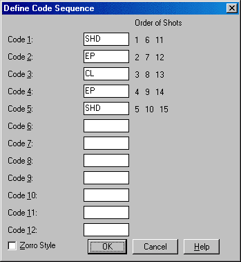
Use Code Sequence: This specifies a sequence type code. Sequences are a way to simplify field entry of a sequence of codes. For example, a road cross-section could be SHD1 EP1 CL EP2 SHD2. Instead of entering these different descriptions, one sequence definition can store these descriptions in order. Then just the sequence code (such as RD) is used in the field. The cross-section can be shot in left to right then left right order, right to left then right to left order, or alternating left to right then right to left order. The alternating method is known as the Zorro style. The one restriction is that the shots always start from a right or left edge. To set up a sequence, choose the Sequence toggle in the Edit Code dialog. Then pick the Define Code Sequence button. This brings up a dialog for entering the sequence codes in order. These sequence codes should be defined as normal codes somewhere else in the Draw Field to Finish code table (ie SHD as a 3D polyline). In the field, the one template code is used for all the cross-sections shots (ie RD for all the points). Then Draw Field to Finish will substitute this template code with the sequence codes (ie substitute RD with SHD).
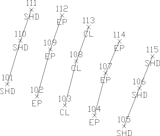 Resulting points and linework showing Zorro style
template
Resulting points and linework showing Zorro style
template
Full Name: This is an optional field that describes the code for viewing.
Description: This value is assigned to the point description attribute when the point is drawn. This description can be different than the field description. An additional description can be added to a point by entering it after a forward slash in the data description field.
Use Raw Description: This option turns off the Description field described above. Instead the points will be drawn with their original unprocessed descriptions. The Attribute Block option applies to the point block with point #, elevation and description fields. The Text Attribute applies to drawing the description as text. The format of the description is controlled by the Attribute Format setting.
Main Layer: The point and line work for the code will be created in this layer.
Distinct Point Layer: When this toggle is selected, the line work is created in the layer defined in the Layer field and the points are created in the specified distinct point layer. For example, you could have DRIVEWAY for linework and DRIVEWAY_PNT for the points.
Dual 3D Polyline Layer: Displays the layer that the 3d polyline will be drawn on when using an Entity Type of 3D and 2D. The layer name can be typed in this field.
Set 3D Layer: Sets the layer that the 3d polyline will be drawn on when using an Entity Type of 3D and 2D. The layer can be selected from the list or typed in at the bottom of the dialog box.
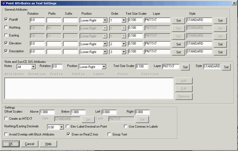
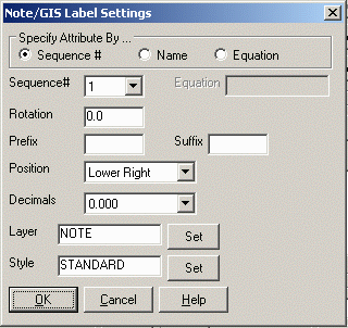
Attribute Format: This chooses the type of point entities to create. The Attribute Block format creates the Carlson point entity which is block with attributes for point#, elevation and description. The Text Attribute format creates text entities for each of the point attributes. When the Text Attribute format is selected, the Set button is available where you can control which attributes to draw as text and the position, order, size, rotation, decimals, style, prefix, suffix and layer for each attribute. The Offset Scalers control the distance for the text from the point for the different positions. These offset distances are calculated by multiplying the scaler by the horizontal scale for the drawing. The Elevation Label Decimal On Point option will place the elevation label so that the decimal point of the label is on top of the point location. The Use Commas In Labels option will add commas for the thousandths place for the northing, easting and elevation labels. The Avoid Overlap With Block Attributes option expands the offset distance starting point from the point to the bounding box that encloses the point block attributes. The Draw On Real Z Axis option controls whether to the text entities at the point elevation or at zero elevation. The Group Text option creates a CAD Group for all the point labels. The Text Size Scaler is multiplied by the current Horizontal Scale to set the text height.
 Also, for
points notes and SurvCE GIS attributes, you can choose to all or
selected fields. For selected, use the Add, Edit and Remove
buttons to build the list of fields to label. To specify the field
to label, the Sequence# method sets the field by its order
position. For example, a sequence of 3 would use the third
attribute for the point. The Name method sets the field to label by
field name such as HRMS. The Equation method sets the value by the
specified equation of attribute names and numbers. Besides the
attribute names, there are keywords of "X", "Y" and "Z" for the
values of the current point coordinates. For example, if there is
an attribute named DEPTH, then you could define a label for the
invert as an equation of "Z - DEPTH". Another example is to make a
label that is 1.5 higher than the point elevation using an equation
of "Z + 1.5". Besides attribute names, you can make an equation by
attribute sequence using "NOTE" plus the sequence number. For
example, if the depth value is the 3rd attribute, then to define a
label for the invert elevation, use the equation "Z - NOTE3".
Also, for
points notes and SurvCE GIS attributes, you can choose to all or
selected fields. For selected, use the Add, Edit and Remove
buttons to build the list of fields to label. To specify the field
to label, the Sequence# method sets the field by its order
position. For example, a sequence of 3 would use the third
attribute for the point. The Name method sets the field to label by
field name such as HRMS. The Equation method sets the value by the
specified equation of attribute names and numbers. Besides the
attribute names, there are keywords of "X", "Y" and "Z" for the
values of the current point coordinates. For example, if there is
an attribute named DEPTH, then you could define a label for the
invert as an equation of "Z - DEPTH". Another example is to make a
label that is 1.5 higher than the point elevation using an equation
of "Z + 1.5". Besides attribute names, you can make an equation by
attribute sequence using "NOTE" plus the sequence number. For
example, if the depth value is the 3rd attribute, then to define a
label for the invert elevation, use the equation "Z - NOTE3".For each attribute, there are settings for the rotation, prefix, suffix, position, decimals, layer and style. The decimals setting applies to GIS fields that are real numbers. Besides labeling attributes as text with this method, the Symbol > Custom Attributes feature is a way to label attributes as block attributes.
Separate Attribute Layers: This controls the layers of the point and symbol attributes and the parent layer for the point attribute block. With "None" the point attribute layers are the standard layers, "PNTNO", "PNTELEV" and "PNTDESC", the parent layer for the point attribute block is the Main Layer and the symbol layer is "PNTMARK". With "Points" or "Both" the point attribute layers begin with the layer for the code followed by the attribute type. For example, the "DWL" code shown in this dialog has a layer name "DRIVEWAY". The point attributes would then be "DRIVEWAYNO", "DRIVEWAYELEV" and "DRIVEWAYDESC". With "Symbols" or "Both" the symbol attribute layer begins with the layer for the code followed by "MARK".
Attribute Layout ID: Controls the location of the point number, elevation and description. These attribute layouts are defined in the drawings that are stored in the Carlson SUP directory with the file name of SRVPNO plus the ID number (i.e. SRVPNO1.DWG, SRVPNO2.DWG, etc.). If you want to change the attribute positions for a layout ID, then open and edit the associated SRVPNO drawing.
Point Groups: This field is for the name of the point group that all points with this code will be added to. If the points for this code belong to multiple point groups, you can specify multiple point group names in this field separated by commas. Under Draw in Additional Draw Options, there is an option whether to automatically use the code name as the point group name or to use the name defined in the code definition.
Text Size Scaler: This is a scaler value that is multiplied by the horizontal scale to obtain the actual size.
Set Color: The line work will be drawn in this color. The default is BYLAYER. The color can be an index or true color.
Entity Type: This defines the line entity to be created. Points only does not create any line work. 3D Polyline can be used for breaklines. 3D and 2D entity type selection creates a 3d polyline in the layer specified in the Dual 3d polyline layer setting and a 2d polyline in the layer identified in the Layer setting. Since 3d polylines do not display linetypes, this is useful when needing linework in 3d for design work while also needing to display linetypes for final plotting of the drawing. This provides an easy and quick way to turn off all 2d polylines or all 3d polylines by using the layer control dialog or the appropriate toggles in the Draw Points dialog.
Elevation Integers: This controls the number of digits to display to the left of the decimal point for the elevation label. The All setting will show the full elevation digits. The other settings allow you to limit the number of digits to display for the purpose of reducing the amount of space the elevation labels take up in the drawing. For example, if a site is in the 4000 foot elevation range, then this setting could be set to three digits (000) and an elevation of 4321 would be labeled as 321.
Elevation Decimals: This controls the display precision for the elevation label.
Elevation Prefix/Suffix: These set the prefix and suffix for the elevation label per code. In the Draw function under Additional Draw Settings, there is an override to set the elevation prefix/suffix for all the codes.
Locate Pts on Real Z Axis: This option will draw the points at the actual point elevation. Otherwise the points are drawn at zero elevation. For example, you could turn this option off for the FH for fire hydrant code to drawn them at zero. Then the GND code could have this option on to draw the ground shots at their elevations.
Non-Surface: Entities created with this flag are ignored when contouring or creating surfaces regardless of their elevation.
Feature Type: Controls how to process this code. The Tree and Pipe types are used for the special tree and pipe processing. All other codes should be set to type Topo.
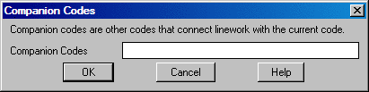
Companion Codes: This option allows different codes to connect when defined as line, polyline or 3d polyline. For example, a main line power pole code may be defined as PP while a service utility pole may be defined as UP. When processing Draw Field to Finish, it may be desired to connect all PP and UP codes together. This could be accomplished by defining a companion for UP as PP and a companion code for PP as UP. Each code needs to reference the other as a companion code.
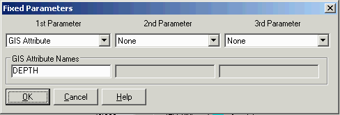
Fixed Parameters: This option is a coding method where you specify a sequence of parameters that follow the main code. There can be up to three parameters and these parameters can be an additional description or special codes Description, GIS Attribute, Size, Rotate, Azimuth, Distance or Offsets. The purpose for Fixed Parameters is to save keystrokes by not having to enter the special code prefix. For example, for a code TR for Tree along with a size 12 feet and description of Oak, the special code description would be "TR SZ12 // OAK". With Fixed Parameters of Size and Description, the description would be "TR 12 OAK".
GIS attributes can be creating using the point description by choosing the GIS Attribute parameter. This way the GIS attributes can follow the main code in the description. For example, you can have a main code of MH for manhole followed by the depth to store as a GIS attribute. In this case, the description would be "MH 4.4".
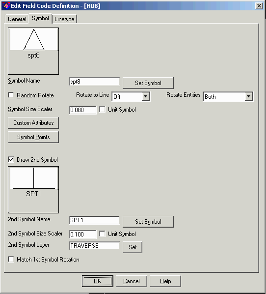
Here are the settings on the Symbol tab:
Random Rotate: This option will randomly rotate the symbol. For example, this option could be used for tree symbols to have the trees drawn in various orientations.
Rotate To Line: This option applies to points that are part of Field-to-Finish linework. This option will align the point attributes and symbol to the associated linework. The Middle mode uses the average angle for the line segments coming to and from the point. The Forward mode uses the line angle going from the point. The Backward mode uses the line angle coming into the point. The Ends mode uses the perpendicular angle for the line end segment and applies for culverts.
Rotate Entities: This setting controls whether to apply rotation to the symbol, the point attribute block or both.
Symbol Size Scaler: This is a scaler value that is multiplied by the horizontal scale to obtain the actual size in the drawing. The horizontal scale can be set in Drawing Setup.
Unit Symbol: This option will draw the point symbol at unit (1:1) scale. For example, this option could be used for a symbol that is already drawn to actual dimensions such as a car symbol.
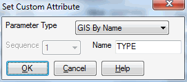
Custom Attributes: This feature allows you to use customized blocks that have customized attributes (the tag/value pairs). This feature works for both point attribute blocks and symbols. For attribute blocks, Field-to-Finish looks for attributes with the tags "PT#", "ELEV2", and "DESC2". The custom attributes feature allows you to define additional attributes in their custom blocks on a per-field code basis. The dialog shows five attributes at a time. The number of attributes is unlimited. Use the Next and Back buttons to show more attributes.
For an example, the custom block could have an attribute with the tag "TREE_SPECIES" and there is a separate field code for each species of tree. Each of those field codes can specify the value that should be assigned to the attribute that has the TREE_SPECIES tag. Then when the points are drawn, the tree species is shown. Note that the custom attributes must have their Constant and Preset properties set to "no". The custom attributes settings in F2F should not use those tags that the software already handles (PT#, ELEV2, and DESC2), or the setting will be ignored.
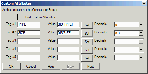
Besides labeling as block attributes, the Attribute Format method of Text mode is a way to label the attributes as text entities.
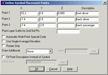
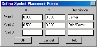
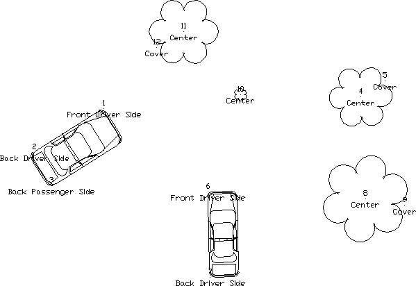
Symbol Points: For each code definition, the symbol insertion points can be defined with up to three points. To define the symbol insertion points, choose the Symbol Pts button in the Edit Code Definition dialog box. By default, the symbol insertion is defined by one point at the symbol center (0,0). A one point insertion definition can be used to insert a symbol offset from the center. With a two insertion point definitions, the program will rotate and scale the symbol. For example, two insertion points can be used to insert a tree symbol to size the tree, where the first point is for the tree center and the second is for the drip line. With three insertion point definitions, the program will rotate and scale the symbol in both X and Y. For example, three points can be used to insert a car symbol with the first point being the front drivers side, the second point as the back driver side (to rotate and scale the length) and the third as the back passenger side (to scale the width). Besides the insertion point coordinates, you can define a description for each point which is used for the drawn point description and is used for prompting in the Insert Multi-Point Symbol command and in Carlson Field data collection.
 Three Point Symbol Drawing
The coordinates for the insertion point definitions are for the symbol at unit size. To figure these coordinates, you will need to open the symbol drawing (.DWG) file. By default, the symbols are located in the Carlson SUP directory. For example to make an insertion point for the tree drip line, open the tree symbol drawing and find the coordinate at the edge of the tree symbol (in this case 0.5,0.0).
 Two
Point Symbol Drawing
Two
Point Symbol Drawing
Not all of
the symbol insertion points need to be used when drawing the
points. If a code definition has a three insertion points, it is
possible to use just the first two or first one. There are special
codes to associate multiple points to the same symbol. The first
code point is used as the first symbol insertion point. The "2ND"
code is used to specify the second symbol insertion point. A point
number can follow the "2ND" to identify a specific point. Otherwise
without the point number, the program will use the next point with
the current code. The "3RD" code is used to specify the third
symbol insertion point and similar to the "2ND" code, a point
number after the "3RD" is optional. The "2ND" and "3RD" codes
should be assigned to the first point. For example, consider a code
of "CAR" with a three point symbol insertion definition. If point
#1 has a description of "CAR 2ND 3RD", then point #1 will be used
as the first symbol insertion point and the next two points with
the "CAR" description will be used as the second and third symbol
insertion points.
 Multi Point Symbol Drawing
The Automatic Multi-Point Special Code option saves from having to enter the 2ND or 3RD special codes. This option applies when the code is always used from multi-point symbols.
The Use Single Average Elevation option averages the elevations of the symbol points for the point elevation label.
The Rotate Only option uses the symbol points only to rotate the symbol and does not scale.
The Draw Additional has options for drawing a 4th point or rectangle. The Create 4th Corner Point option draws another point when using a three multi-point symbol. This option applies when the symbol is rectangular and you shoot three corner points and want the program to draw a point at the 4th corner. The Rectangle option creates a rectangle to fit the 3 symbol points and applies to creating a breakline for surface modeling around the symbol.
The Fit Point Description Instead Of Symbol option is a method to drawing labels that are positioned by these points such as road markings. To set a custom text to label, you can use the /// (Replace Description) special code. For example with a code called MARK, the description could be "MARK 3RD ///BUS LANE". Or turn on the Automatic Multi-Point Special Code and then the “3RD” isn’t needed and the description could be "MARK///BUS LANE". For the text control points, lower-left = 0,0, upper-right = 1,1, upper-left=0,1, and lower-right = 1,0.
Draw 2nd Symbol: This option creates a second symbol on each point. This additional symbol can be used to add a 3D symbol to a 2D symbol used as the first symbol. Besides selecting the symbol name, there are settings for the symbol size and layer.
Here are the settings on the Linetype tab:
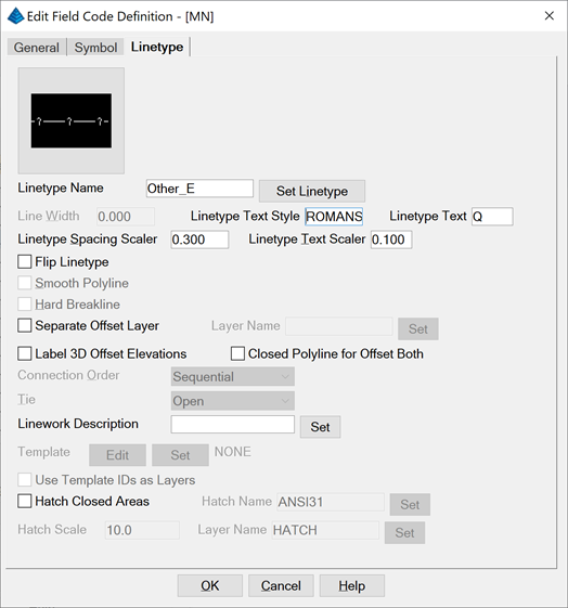
Set Linetype: Line work can be drawn in any of the special linetypes or with the linetype for the layer ("BYLAYER"). There are three types of pre-defined linetypes: CAD, Entity and Continuous. The type is shown as part of the linetype names in the list. The CAD linetypes are the default linetypes available in AutoCAD and IntelliCAD. The Entity linetypes insert text or symbol entities at the linetype interval. These linetypes are the same as used with the Annotate->Polyline To Special Line command. The Continuous linetypes define a special linetype in CAD and create continuous polylines with that special linetype. These linetypes are the same as with the Annotate->Change Polyline Linetype command. Besides these pre-defined linetypes within Field-to-Finish, you can also use any linetype that is defined in the drawing by entering that linetype name in the linetype edit box or by picking the Select From Drawing button within the Set Linetype dialog. The spacing and size of the special linetypes is determined by the CAD LTSCALE system variable and by the field code settings Line Type Spacing Scaler and Line Type Text Scaler. The special linetype "hedge" is drawn with a width set by Line Width. The special linetype "userdash" is drawn with user specified distances for the length of the dash and the length of the gap between dashes.
Line Width: This controls the width for the linework. Only applies to 2D polylines. The LTW special code can also be used to set the line width for a specific line.
Linetype Text: This is the text that is used for the user-defined linetype. First use Set Linetype to either Other_E or UserDef_C. Then this text will be used for the linetype. For example, if you have a code for a 8" PVC pipeline, then you could set this text to 8" PVC. This linetype text will use the font set in the Linetype Text Style. If this style is blank, the text will use the current font.
Linetype Spacing Scaler: This is a scaler value that is multiplied by the CAD LTSCALE system variable to give the distance between symbols in the line.
Linetype Text Scaler: This is a scaler value that is multiplied by the CAD LTSCALE system variable to give the size of the text in a line.
Closed Polyline for Offset Both: This option will create a closed polyline from the left and right offset polylines when the OFB (Offset Both) special code is used.
Flip Linetype: This option switches the side for the linetype which applies to non-symmetrical linetypes like the treeline or guard rail.
Smooth Polyline: This option applies a modified Bezier smoothing to the polyline. The smoothed polyline will pass through all the original points.
Hard Breakline: This option will tag the 3D polylines created with this code as hard breaklines. In Triangulate & Contour, contours are not smoothed as they cross hard barriers.
Separate Offset Layer: This setting uses another layer name for polylines created using an offset special code.
Label 3D Offset Elevations: This option labels the elevations and symbols of the vertices for polylines created using an offset special code.
Connection Order: The points of a distinct code can be connected in their point number order or by nearest found which makes the line by adding the next closest point.
Tie: When checked the linework drawn with this code will always close. For example if you have points 1, 2, 3, and 4 with the code BLDG and Tie is checked on for the code BLDG, then the linework will be drawn from point 1 to 2 to 3 to 4 and then back to point 1, closing the figure.
Linework Description: This description is labeled along linework created by this code. The Set GIS button chooses a GIS attribute to use for the linework description. The program checks all the points used for the linework for the GIS attribute for this description. The Description Setup button displays a dialog to control the layer, style and size for these labels. You can also set the label interval. The Flip Text For Twist Screen option orients the linework labels to be right side up for the drawing current twist view. The Add Point Special Descriptions adds any point special code descriptions to the Linework Description.
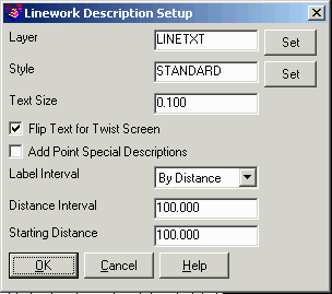
Edit and Set Template: For 3D polyline codes, this option allows you to assign a template (.TPL) file to the code. The code points act as the centerline for the template and the program will draw parallel 3D polylines for each break point (grade ID) in the template. The template file is defined in the Civil Design module or by using the Edit button. In the Edit Template dialog, there's a special setting for Field-to-Finish for the Offset Target Grade. This Offset Target Grade controls which grade in the template to use as the centerline for the code points. If this field is blank, then the start of the template is used.
The templates are dynamic and can be adjusted along the 3D polyline by using the OH (offset horizontal) and OV (offset vertical) special codes. For example, when there is a curb template that flattens when it comes to a driveway, then an OV0 code could be used at the driveway start point and then use OV.5 at the driveway end point to restore the curb to 0.5 feet high.
The Use Template IDs as Layer option will use the grade IDs from the template for the layers of the 3D polylines.
Hatch Closed Areas: This option applies for codes used to draw closed linework. This linework can be used as the perimeter for a hatch area. The hatch settings include the hatch pattern name, scale and layer.
Code Definitions (continued)
Select All: This option selects all the codes. This can be used when only wanting to process a couple of codes. For example, use the select all option to select all the codes and then turn them off. Now select the codes for processing and turn them on. Also it can be used to make a global change to all the codes.
Add: The new code definition is inserted in the list in the position after the currently selected one. If none are selected for positioning, the new code is placed at the top. Only one code definition may be highlighted before running this routine.
Copy: This option copies the definition of a selected code. It opens the Edit Field Code Definition dialog and copies the definition of the selected code to the appropriate settings. It does not copy the name of the code. It is a time saving tool to use when creating codes that are similar with only a couple of differences.
Cut: This command will remove the highlighted code definitions from the list and puts them in a buffer for retrieval with Paste.
Paste: This command will insert the code definitions put in the buffer by the Cut command. These codes will be inserted after the row of the currently highlighted code or at the top.
Search: Allows you to search for a specific code in the list.
Coordinate File
Set CRD File: This command allows you to specify a coordinate (.CRD,.CGC,.MDB,.ZAK) file to process.
Edit Points: This command opens the Edit Points spreadsheet editor. See Edit Points for more details.
Draw:
This command
returns to the Draw Field to Finish dialog box.
Coding Examples
Under the Carlson Projects folder, there is an example that shows the different ways for linework coding along with examples for many of the special codes. The examples are in f2f_example.crd and f2f_example.fld. Here is a breakdown of the features that the points illustrate.
Point 1: Point Entity by itself
Points 2-3: Using Begin code to start a line; end line using Begin
code for next line
Points 4-5: Using Begin and End to start and stop linework
Point 6: Point Entity by itself after End code
Points 7-11: Linework by code defined as Polyline entity type;
using End as break between linework
Points 12-15: Linework by code defined as Polyline entity type;
using Begin as break between linework
Points 16-19: Linework by code defined as Polyline entity type;
using # after code instead of Begin/End to separate linework
Points 20-22: Linework by code defined as Polyline entity type
without using Begin/End to start/stop linework
Points 24-26: 3 point curve using on PC code
Points 27-30: 3+ point curve using PC/Point codes
Points 32-33: 2 point tangent curve using PC/Point codes
Points 35-39: reverse curve using PC/Point codes
Point 40: Regular point without extra descriPointion
Point 41: Using // to use a code descriPointion as a suffix
Point 42: Using \\ to use a code descriPointion as a prefix
Point 43: Using / to append a descriPointion
Point 44: Using \ to add a descriPointion as a prefix
Point 45: Using ROT and a Point# to rotate to that Point#
Point 46: Using ROT and a value to set the rotation
Point 47: Using ROT by itself to rotate to the next Point#
Point 48: Regular point without rotation
Point 49: Using AZI and DIST codes to offset the point
Point 50: Using SZ with value to set size of symbol
Points 51-52: Using SZ by itself to size symbol by the distance to
the next point
Point 53: Using SZ with 2 values to draw multiple symbols at those
sizes
Points 54-55: Using 2ND code to size the symbol
Points 56-58: Using 2ND and 3RD codes to size the symbol in 2
dimensions
Points 59-62: Using CLO to close the linework
Points 63-64: Using RECT with two points and a value to create a
rectangle
Points 65-67: Using RECT with three points to create a
rectangle
Points 68-69: Using OH to offset right a fixed amount
Points 70-73: Using OH on multiple points to offset various
amounts
Points 74-75: Using multiple OH on the same point to offset
polyline multiple times
Points 76-77: Using OH with negative value for offset to left
Points 78-79: Using OFL with value for offset left a fixed
amount
Points 80-81: Using OFB with value to offset both left and right a
fixed amount
Point 82: Using CIR to draw circle at specified radius
Points 83-84: Using CIR to draw circle using two points for center
and perimeter
Points 85-89: Using CIR to draw best-fit circle through points on
perimeter
Points 90-91: Using JPN to join linework to another Point#
Points 92-95: Using SMO to create smoothed linework
Points 96-97: Using JOG to create additional linework segment
extensions
Points 98-102: Using GAP to create a break in the linework
Points 103-106: Using LFT to switch linetype to left side
Points 107-109: Using WALL3D with specified height value
Points 110-112: Using WALL3D with height from 2nd point
Points 113-115: Using BLOCK3D with height and three points to
define parallelogram
Points 116-123: Using BLOCK3D with height and multiple points to
define perimeter
Points 124-128: Using FACE3D with multiple points to make a
surface
Points 129-132: Using HOLE3D with multiple points to define the
perimeter of a hole in the FACE3D surface
Point 133: Using code definition with Attribute Format set to Text
and only Elevation turned on with Label Decimal On Point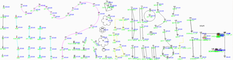 PointCAD
Coding
PointCAD
Coding
Field-to-Finish supports an early Carlson style of linework coding
called PointCAD. The PointCAD codes use numbers with +,-,* symbols
as follows:
+0 Starts a regular 2D line (not a polyline)
that is open.
*0 Starts a regular 2D line that is closed.
+4 Starts a curved 2D polyline that is open.
*4 Starts a curved 2D polyline that is
closed.
+1 Begins a 3-point arc.
-0 or -1 or -3 or -4 or -5 or -6 or -7
Ends a line.
+5 Starts a 3D polyline that is open.
*5 Starts a 3D polyline that is closed.
+6 Starts a 2D polyline that is open.
*6 Starts a 2D polyline that is closed.
+7 starts line whose type (2D line, 2D polyline,
3D polyline) is specified by the point's field code
definition. If the field code definition is to use points,
then a 2D line is started.
+2 Middle point of 3 point arc
-05 starts a curved 3D polyline section.
-50 ends a curved 3D polyline section.
+8 starts a 2D and 3D polyline combination that
is open.
*8 starts a 2D and 3D polyline combination that
is closed.
-8 ends a 2D and 3D polyline combination.
-08 starts a 2D and 3D polyline combination
curve that is open.
-80 reverts back to a straight 2D and 3D
polyline combination.
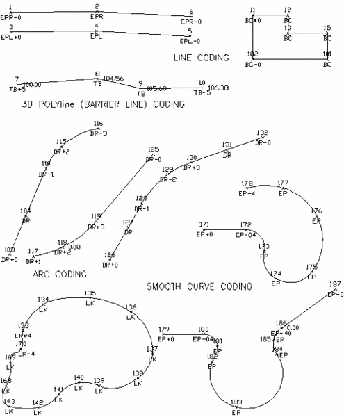 PointCAD
linework coding examples
PointCAD
linework coding examples
With GIS processing activated, the entities created by Field-to-Finish are linked to a GIS feature name and attributes. These GIS links can be used by the routines in the GIS module such as GIS Data Editor.
GIS processing in Field-to-Finish starts with the GIS Table setting in the initial Draw Field To Finish dialog. The GIS Table is the .GIS file created by the Define GIS Features command which defines the GIS feature names and attributes. Setting the GIS Table is optional but useful. The GIS Table is used as the reference in the Set functions for selecting a GIS feature name to assign to Field-to-Finish codes. Additionally, when processing the Field-to-Finish codes, any associated attributes from the GIS Table will be attached to the entities. Also, attributes generated from Field-to-Finish are added to the GIS Table. So using the GIS Table links the GIS module commands with Field-to-Finish.
Each Field-to-Finish code has settings to assign GIS feature names. In the Edit Field Code Definition dialog, the GIS Setup button brings up a dialog for setting the GIS feature names and attribute options for the current code. Since Field-to-Finish codes are capable of drawing both points and linework and GIS can have different features for points and linework, there are separate settings for the GIS feature names for points and linework. For example, a Field-to-Finish code UP for utility pole could be setup to draw both points with symbols at the poles and polylines between these points. Then you could have different GIS feature names for the pole points and linework with separate GIS attributes for each.
For Attributes to Create, these options create GIS attribute data which is stored in the database setup by the GIS Settings command and linked to the entities created by Field-to-Finish.
SurvCE GIS Fields: This option uses the attribute data generated by SurvCE which is stored in a .vtt file with the same file name as the current coordinate file except with the .vtt extension.
Field-to-Finish Code: This option creates an attribute named CODE with a value of the Field-to-Finish code name (ie. UP).
Field-to-Finish Full Name: This option creates an attribute named FULL_NAME with a value of the Field-to-Finish Full Name (ie. Utility Pole).
Special Codes: This option creates attributes for Field-to-Finish special codes including OH (Offset Horizontal), OV (Offset Vertical), SZ (Size), ROT (Rotation), AZI (Azimuth) and DIST (Distance).
Point Number: This option creates an attribute named POINT_NAME with a value of the point number from the coordinate file.
Drawing Description: This option creates an attribute named POINT_DWG_DESC with a value of the point description for the point block created in the drawing.
Coordinate File Description: This option creates an attribute named POINT_RAW_DESC with a value of the point description from the coordinate file.
The Point Properties By GIS Parameters lets you control the layer, symbol, linetype, color or size of the points based on GIS attributes. A classic example is drawing cities on a map with different symbols and sizes based on the population. The properties are defined in order of priority so that the first to match the parameters is used. Use the Up and Down buttons to change the order of the properties.
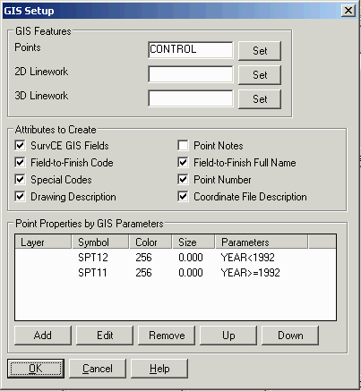
Default Code Tables
Default code tables are installed under Carlson Projects\Settings including Carlson.fld and the following DOT's: CA, CO, FL, IA, IL, IN, LA, MA, MD, MN, MO, MS, NC, ND, NE, NY, OH, SD, SK, TX, WA and WI.
Pipe Surveys
The Pipe Feature adds additional properties to the pipe of size, material and name. Also the Pipe Feature allows for more labeling of the pipe parameters and ability to draw the pipe in 3D.
Important: The Pipe Settings apply to codes that are set to a Feature Type of Pipe. To set the Feature Type, go to Edit Codes and then the General tab of the Edit Field Code Definition dialog.
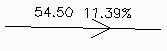 When a code is tagged as a Pipe
Feature, the program looks for additional parameters after the
code. The parameters are separated by spaces in the point
description and in the order specified in the Description Sequence
in the settings dialog. For example, if code 'P' is defined as a
Pipe Feature and the order of size, material and name, then a
description of 'P 8 PVC 31' would define a pipe point for an 8 inch
pipe of material PVC and name of 31. These pipe parameters are
optional. The program will use the provided parameters and leave
the rest blank. Besides using the point description, the pipe
attributes can be set from GIS attributes using the attribute names
setup in the dialog.
When a code is tagged as a Pipe
Feature, the program looks for additional parameters after the
code. The parameters are separated by spaces in the point
description and in the order specified in the Description Sequence
in the settings dialog. For example, if code 'P' is defined as a
Pipe Feature and the order of size, material and name, then a
description of 'P 8 PVC 31' would define a pipe point for an 8 inch
pipe of material PVC and name of 31. These pipe parameters are
optional. The program will use the provided parameters and leave
the rest blank. Besides using the point description, the pipe
attributes can be set from GIS attributes using the attribute names
setup in the dialog.For a structure with multiple inverts, the invert values should be in the description separated by commas. For example, for a structure with two incoming PVC pipes with sizes of 15" and 24", and inverts at depths 5.9 and 5.5, the description would be 'P 15,24 PVC 5.9,5.5'.
The Create Pipe Network option will generate a .sew data file that is used by the Hydrology > Network commands. The Connection Distance Tolerance is the max distance between pipe points to be counted as connecting to the same structure. The Use Point Elevation setting controls whether to use the point elevation for the pipe invert elevation or the structure rim elevation. When using the Create Pipe Network to create multiple unconnected pipe networks, each separate pipe network must have separate codes. For example, if PIPE is your pipe feature code and you are creating two pipe networks, all the points on one pipe network could use code PIPE1 and the other network PIPE2.
The Invert Measurement sets whether the inverts are measured to the top or bottom of the pipe. When measuring to the top of pipe, use the Pipe Thickness Lookup to define the default pipe thickness and pipe thickness for different pipe sizes and materials. The program will use the pipe thickness plus the pipe size to calculate the invert for the bottom of the pipe.
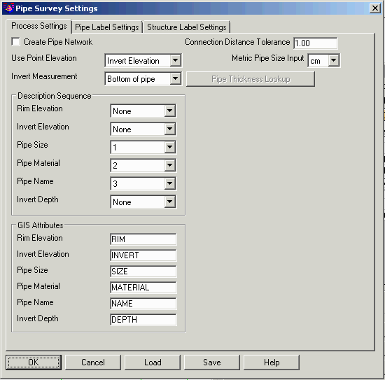
To setup the label and draw options, pick the Pipe Setup on the main edit codes dialog and pick the Pipe Label Settings tab. There are options to label the pipe length, size, material, name and slope. Under Draw Pipe Type, there are different styles for drawing the pipe line. The 3D Faces option draws the pipe in 3D at the pipe size. The Field-To-Finish option uses the polyline type (2D or 3D) as defined by the Field-to-Finish code. The Use Field-to-Finish Code Layer option uses the layer from the code definition instead of the pipe settings layers.
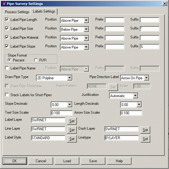 The Structure Label Settings tab has
settings for labeling the structures in plan view. See the Plan
View Label Settings topic in the Hydrology chapter for information
on these settings.
The Structure Label Settings tab has
settings for labeling the structures in plan view. See the Plan
View Label Settings topic in the Hydrology chapter for information
on these settings.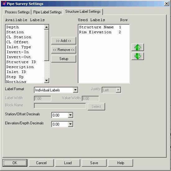 Example coding of a pipe network.
PIPE code is defined as a Pipe Feature. The 1st description is the
pipe size. The 2nd description is the pipe material. The 3rd
description is the pipe depth. Point 3 has two sizes and two depths
separated by commas because two pipe connect at this point.
Example coding of a pipe network.
PIPE code is defined as a Pipe Feature. The 1st description is the
pipe size. The 2nd description is the pipe material. The 3rd
description is the pipe depth. Point 3 has two sizes and two depths
separated by commas because two pipe connect at this point.| Point |
Description |
| 1 |
PIPE1 15 HDPE 4.75 |
| 2 |
PIPE1 15 HDPE 6.15 |
| 3 |
PIPE1 15,24 HDPE 5.96,5.5 |
| 4 |
PIPE1 24 HDPE 9.9 |
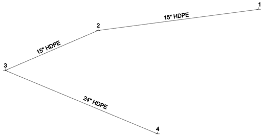
Example coding for 2 separate pipes using END code to separate the pipes. CUL code is defined as a Pipe Feature. 1st description is the Pipe Material and 2nd description is the pipe size. In this case, turn OFF the Create Pipe Network because the separate pipes are using the same code of CUL.
| Point |
Description |
| 7 |
CUL RCP 18 |
| 8 |
CUL END RCP 18 |
| 14 |
CUL RCP 18 |
| 15 |
CUL END RCP 18 |
Example coding for 2 separate pipes using number suffix on codes to separate the pipes. CUL code is defined as a Pipe Feature. 1st description is the Pipe Material and 2nd description is the pipe size. In this case, the Create Pipe Network can be applied. The separate pipes are using separate codes of CUL1 and CUL2.
| Point | Description |
| 7 |
CUL1 RCP 18 |
| 8 |
CUL1 RCP 18 |
| 14 |
CUL2 RCP 18 |
| 15 |
CUL2 RCP 18 |
Tree Surveys
Tree surveys can be coded simply by using general Field-to-Finish coding methods such as defining a code for a tree ("OAK") with a tree symbol and using the SZ special code for sizing the symbol. For tree survey specific features, go to the Tree Survey button on the main edit codes dialog. This function brings up a dialog with tree survey settings. The tree survey works with three attributes for each tree: trunk, drip and tag. Trunk is the diameter of the tree trunk. Drip is the radius of the tree canopy. Tag is an id for the tree for reporting.
Important: The Tree Survey Settings apply to codes that are set to a Feature Type of Tree. To set the Feature Type, go to Edit Codes and then the General tab of the Edit Field Code Definition dialog.
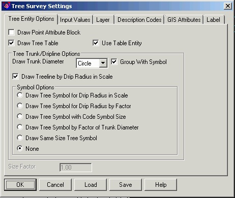
On the Tree Entry Options dialog tab:
Draw Point Attribute Block: controls whether to draw the point block with the point #, elevation and description attributes.
Draw Tree Table: This option makes the program prompt for whether to draw a tree table when the program finds a couple points with tree codes. Otherwise, there must be many tree codes to have the program prompt for creating a tree table. The Use Table Entity option draws the table as a Carlson Table Entity. Otherwise the table is drawn with regular CAD lines and text.
Draw Trunk Diameter: Sets whether to create a circle or solid with the trunk diameter. The Group With Symbol option creates a CAD group to combine the tree and trunk symbols.
Draw Treeline by Drip Radius in Scale: shrinkwraps the tree driplines to get the overall treeline perimeter. The perimeter polyline can be drawn either as Bubbles or Smooth. The Bubbles creates a treeline style polyline with a series of arcs. The Smooth creates a regular polyline.
Codes to Skip Treeline: allows you to skip specific Field-to-Finish codes from using with the treeline. If you have more than a single code to skip, use either a space or comma to separate the codes.
Draw Tree Symbol for Drip Radius in Scale: draws individual symbols for each tree using the symbols defined in the code table and scaled by the drip size attribute.
Draw Tree Symbol for Drip Radius by Factor: draws individual symbols for each tree using the symbols defined in the code table and scaled by the drip size attribute and the Size Factor from this dialog.
Draw Tree Symbol with Code Symbol Size: draws individual symbols for each tree using the symbol name and size defined in the code table.
Draw Tree Symbol by Factor of Trunk Diameter: draws individual symbols for each tree using the symbols defined in the code table and scaled by the trunk size attribute multiplied by 12. For example, a 10" trunk size is drawn as a 10ft symbol.
Draw Same Size Tree Symbol: draws individual symbols for each tree using the symbols defined in the code table and at size of 6.
None: simply does not draw a tree symbol
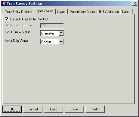
On the Input Values Options dialog tab:
Default Tree ID to Point ID: This option uses the point number for the tree tag unless the point description contains a tree tag.
Begin Tree ID From: This is the number to start incrementing tree tags from in case the tree coding is missing tags and you want to assign tags for reporting.
Input Trunk Value: controls whether the trunk size is entered as a radius or diameter.
Input Drip Value: controls whether the canopy drip size is entered as a radius or diameter.
Canopy Companion Code: this tree coding method handles a point at the trunk and then a series of 3 or more points for the canopy. The point description coding uses separate codes for the trunk and the canopy points. The program draws a Bezier smooth polyline thru the points for the canopy. In this example, points 1 and 6 have the tree feature code from the Field-to-Finish code table, and the rest of the points have the Canopy Companion Code.
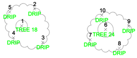
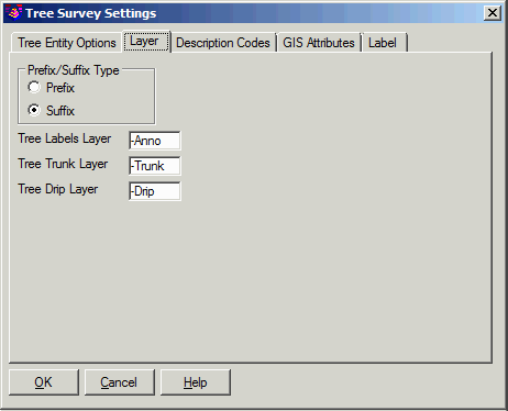 On the Layer
dialog tab, there are optional layer names for different types of
tree entities to append either as a prefix or suffix to the layer
from the code table.
On the Layer
dialog tab, there are optional layer names for different types of
tree entities to append either as a prefix or suffix to the layer
from the code table.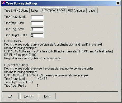 On the
Description Codes tab,
there are setting to help identify the tree attributes in the point
description. The program looks for the trunk size, drip size, tag
ID and height in the point description after the tree code. By
default, the program expects the attributes to be in the order of
trunk size, drip size, tag ID and height. Here's an example default
order:
On the
Description Codes tab,
there are setting to help identify the tree attributes in the point
description. The program looks for the trunk size, drip size, tag
ID and height in the point description after the tree code. By
default, the program expects the attributes to be in the order of
trunk size, drip size, tag ID and height. Here's an example default
order:OAK 16 12 100 28
where OAK is the tree code from the code table, 16 is the trunk diameter, 12 is the drip radius, 100 is the tag ID and height is 28.
If the attributes are in a different order, then the suffix/prefix settings can be used to identify the attributes. When the program finds a specified prefix or suffix, that tells the program which attribute to use. For example, if the Trunk Suffix is "in" and the Drip Suffix is "ft" and the Tag Prefix is "T", then
OAK T100 16in 12ft
means tag ID of 100, trunk diameter 16 and drip radius 12 feet.
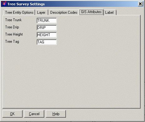 In addition
to looking for the tree attributes in the point description, the
program can also read these attributes from GIS fields. On the
GIS Attributes dialog tab,
you can set the GIS field names for the tree attributes.
In addition
to looking for the tree attributes in the point description, the
program can also read these attributes from GIS fields. On the
GIS Attributes dialog tab,
you can set the GIS field names for the tree attributes.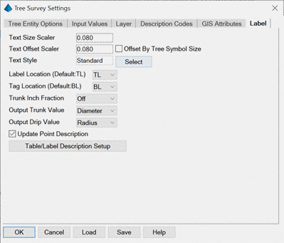
On the Label tab, there are settings for the tree text labels for the size, offset from trunk center, style and location. When creating a tree table, only the tag text is labeled. Otherwise, the label is drawn.
Offset By Tree Symbol Size moves the labels beyond the tree symbol to avoid overlap between the labels and the symbol.
Trunk Inch Fraction sets the inch precision to use for the trunk size labels.
Output Trunk Value sets whether to label the trunk size as a radius or diameter.
Output Drip Value sets whether to label the canopy size as a radius or diameter.
Update Point Description sets whether to only use the label setup for the table and not the point description.
The Table/Label Description Setup dialog sets which fields to include in the label or table. For each field, there are settings for the field order, prefix, suffix and decimals. The New Row option allows for drawing labels on separate rows. The Header and Width settings are for the tree table. The Only Label Tag ID With Table option controls whether to draw the tree tag when not creating a tree table.
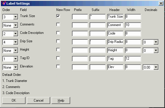 When
Field-to-Finish draws entities, the program checks for codes set as
tree features and applies the settings from the Tree Survey dialog.
When tree features are found, the number of trees are reported
along with a prompt for whether to draw a tree table. The tree
table has the tag ID, code description and trunk diameter.
When
Field-to-Finish draws entities, the program checks for codes set as
tree features and applies the settings from the Tree Survey dialog.
When tree features are found, the number of trees are reported
along with a prompt for whether to draw a tree table. The tree
table has the tag ID, code description and trunk diameter.Here is an example with the following three points:
Point# Northing Easting Description
1 4994.73 4923.15 OAK 24 38 301
2 5034.59 4881.40 PINE 18 24 302
3 4987.32 4975.79 PINE 12 20 303
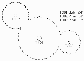 Dripline drawn as Treeline method along with a tree
table.
Dripline drawn as Treeline method along with a tree
table.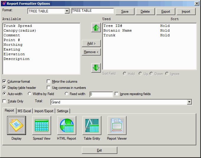 Tree ID Botanic Name Trunk
T301 Oak 24"
T302 Pine 18"
T303 Pine 12"
Pulldown Menu Location: Survey
Keyboard Command: fld2fin
Prerequisite: A data file of points with
descriptions