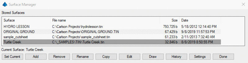
The Surface Manager toolkit allows you to modify pre-defined triangulated surfaces, making real-time modifications and updates to contours and associated TIN (Triangulated Irregular Network) definitions. Functionality includes swapping TIN lines, adding or removing (untagging) breaklines, adding or removing points by range or group, adjusting point elevations, removing TIN lines, drawing or removing contour lines and labels, re-contouring at a different interval or with different label settings, etc. Contour lines are automatically updated to reflect any changes made to the TIN. A surface must be named and saved by of one of the surface modeling routines (in the Triangulate tab) as a prerequisite to using the Surface Manager.
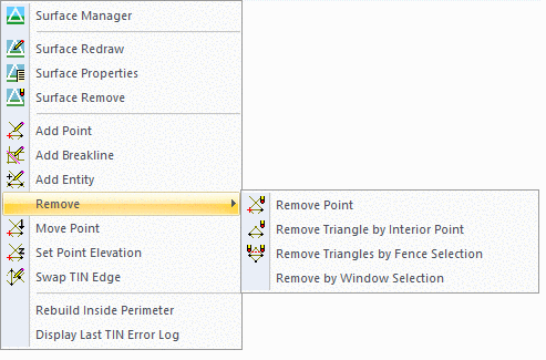
All of the tools available in the Surface Manager are also
available in the fly-out menu, as shown in this figure. Their
functions are identical but require a surface to be set current.
Changes made apply only to the current surface.
Set Current Designates a surface as current for editing
with various surface tool functions, such as modifying TIN lines,
setting a new contour interval, labeling contours, etc.
Add Allows you to add a surface by selecting a surface
model file (.TIN or .FLT).
Remove Allows you to remove a surface from the list of
stored surfaces.
Rename Allows you to rename a surface.
Copy Creates a copy of the TIN file and adds the copy as
a new entry.
Edit Displays various edit tools. Clicking on any of
these commands will activate the command line, where you will be
prompted based on the Edit command selected.
Draw Allows you to alter the drawing display properties
for TIN lines, contours and labels for the selected surface.
Applicable dialogs from Triangulate and Contour are used to provide
a full set of options. When accessed, settings for the current
surface display configuration are set. To make a modification,
simply specify the desired change and press ok. For instance, if
Draw Triangulation Lines was checked on, unchecking the box and
pressing ok will redraw the surface without the TIN lines. If the
contours were drawn at 1 foot intervals, setting the interval value
to 2 and pressing OK will redraw the contours at 2 foot intervals.
Refer to the Triangulate and Contour section of the manual for a
more detailed explanation of the options.
History The Triangulation History Editor displays all
functions performed during the creation and editing of a TIN file.
Each edit can then be eliminated from the process without
recreating the TIN from scratch. In cases where the user does
recreate the TIN, any edits previously performed can be recalled
and re-implemented.
Settings Allows you to set the triangle edge and
breakline Color and Transparency for easier editing. Many times the
triangle edges or breaklines can get lost or match colors for say
the contours and this allows you to better differentiate the items
when editing.
The dialog for this function has the pulldown with the choice of
the editing operation. You can pick it from the pull-down or type
the corresponding keyword at the command line to switch.
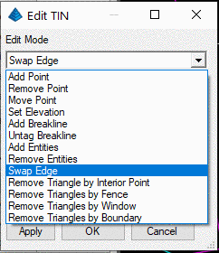
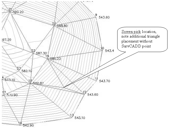
Add Point (AP) prompts to pick point or point number to
add [Group/Range]. This allows you to adds triangulation point(s)
to the network by either graphically picking points from the
screen; typing a point number; or by adding an entire (R)ange or
point (G)roup to the TIN. You can add points to the inside or the
outside of the TIN. The elevation for graphically selected points
is interpolated from the surrounding TIN network. This is a good
method for adding additional triangulation to the surface in a
sparse area. Also, a new elevation can be specified for the picked
point. There is an option for whether to store the graphically
selected point to the coordinate file. When 3D polylines are
created by Field to Finish and you add point by range or point
group that covers the point numbers used to make the 3D polylines,
then the segments from these 3D polylines are used as breaklines in
the TIN.
Remove Point (RP) removes an existing triangulation
intersection from the TIN network. The affected triangulation
re-adjusts to compensate for the missing intersection. Contours
update accordingly.
Move Point (MP) is a combination of removing a point and
adding it at a new location.
Set Elevation (SP) sets a new elevation for a specified
TIN intersection. The affected TIN is adjusted and the contours are
updated.
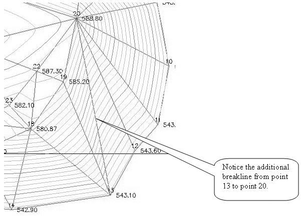
Add Breakline (AB) adds a breakline to the surface by
picking beginning and ending points on the screen. The endpoint
snap automatically turns on. Only one breakline can be created at a
time. The TIN network will reconfigure to follow the new breakline
and update the contours. This does not create 3d polylines in the
drawing.
Untag Breakline (UB) removes breaklines from the TIN that
were either added through Add Breakline Edit command or through the
initial selection of lines in the drawing.
Add Entities (AE) adds selected points and breaklines
into the TIN by graphical selection of existing entities on
screen.
Remove Entities (RE) removes selected points and
breaklines from the TIN by graphical selection of entities used in
its creation.
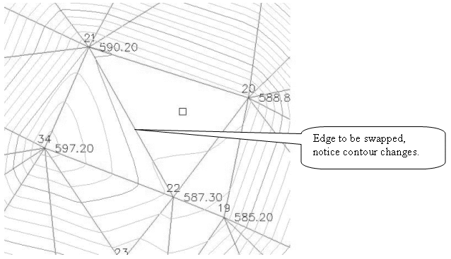
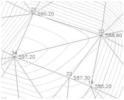
Swap Edge (SW) swaps common TIN edges to create two
different triangles from the original triangle configuration.
Contours automatically update to reflect changes made to the TIN.
Some common edges may not be swapped because of the orientation of
the two triangles.
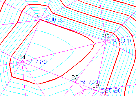
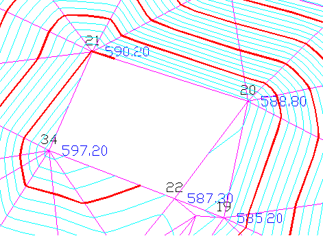
Remove Triangle by Interior Point (RT) removes a TIN line
from the surface by picking a TIN line or selecting an interior
point. Contours are removed from the affected area.
Remove Triangles by Fence (RF) removes existing triangles
that touch the fence as it is being drawn across the
triangles.
Remove Triangles by Window(RW) removes existing triangles
using a crossing-type window whereby any triangles that touch or
are contained within the window when drawn will be removed.
Remove Triangles by Boundary(RB) removes existing
triangles that touch or are contained within a selected closed
boundary or polyline.
Add Pnt(AP),Move Pnt(MP),Set elev(SP),Add Breakline(AB),Untag Breakline (UB), Add Entities(AE),SWap edge(SW),ID Pnt(ID),Show/Hide Tris(ST), Remove Pnt(RP),Remove Tri(RT),Remove Entities(RE),Remove by Window(RW),Remove by Fence(RF),Remove by Boundary(RB),Update Tris(UT) Press Enter to end. Press Esc to cancel.
Add Pnt(AP)
Pick point or point number to add [Group/Range]: Graphically pick points from the screen; type a point number; or add an entire (R)ange or point (G)roup to the TIN. When graphically selecting a point, you will be prompted for the elevation of the new point, and if you would like to add the new point to the current coordinate file.
Move Pnt(MP)
Pick near point to move: Graphically pick near a point to move. Carlson will take that point and place it in a new location when prompted.
Set elev(SP)
Pick near point to set elevation: Graphically pick near a point to change the elevation and you will be prompted for the new elevation.
Add Breakline(AB)
Pick point or point number for 1st breakline point: Graphically snap 2 points on the screen for the new breakline.
Untag Breakline(UB)
Select an breakline edge to untag: Graphically select a triangle edge that represents a breakline to remove.
Add Entities(AE)
Select points and breaklines to add to triangulation. FILter/Select entities: Graphically select entities to add to the TIN by pick or window selection.
SWap edge(SW)
Select an internal edge to swap: Graphically pick near a Triangle Edge to swap. This will switch the direction of two triangles sharing the same edge.
ID Pnt(ID)
(Prompt is from current edit command) The coordinates of the nearest triangle vertex are displayed on the commandline (Point: x=, y=, z=).
Show/Hide Tris(ST)
(Prompt is from current edit command) Temporarily toggles the display of the triangles ON or OFF the screen for easier editing.
Remove Point(RP)
Pick point to remove: Graphically pick near a point you with to remove from the TIN.
Remove Tri(RT)
Removing Triangles, Pick point or enter keyword: Graphically pick inside a triangle you wish to remove.
Remove Entities(RE)
Select entities to remove from triangulation. FILter/Select entities: Graphically remove breaklines, points, etc. that were used in the creation of the TIN that you want to remove from the TIN. This will reform the TIN without the selected entities.
Remove by Window(RW)
Pick 1st corner of area to remove: Graphically select 2 points of a window. Any TIN triangles inside or touching the window selection will be removed from the TIN.
Remove by Fence(RF)
Pick beginning of fence: Graphically select points on a screen to create a fence. Any TIN triangles touching the fence selection will be removed from the TIN.
Remove by Boundary(RB)
Select boundary polyline: Graphically select a closed polyline. Any TIN triangles inside or touching the polyline will be removed from the TIN.
Update Tris(UT)
(Prompt is from current edit command) Refreshes the TIN drawn on the screen from the TIN file.
To conclude the Surface Edit mode, press Enter at the end of the
internal command sequence. This will return to the Surface Manager
dialog. If you press Escape key instead, the following dialog is
displayed:
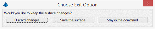
This prevents you from accidentally undoing all of your changes
by unintentional pressing the ESC key.
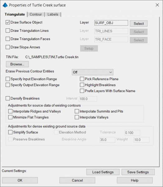
(Draw) Properties allows you to draw the surface and control the
properties for the TIN lines, contours and labels for the selected
surface. Applicable dialogs from Triangulate and Contour are used
to provide a full set of options. When accessed, settings for the
current surface display configuration are set. To make a
modification, simply specify the desired change and press ok. Refer
to the Triangulate and Contour section of the manual for a more
detailed explanation of the options.
The Triangulation History Editor displays all functions
performed during the creation and editing of a TIN file. Each edit
can then be eliminated from the process without recreating the TIN
from scratch. In cases where the user does recreate the TIN, any
edits previously performed can be recalled and re-implemented. For
example, if you have added several breaklines and later decide that
they were unnecessary, highlight the added breaklines and click
Remove Entry. You can also change the order in which an edit
appears, such as the application of an exclusion boundary toward
the end of the list of edits.
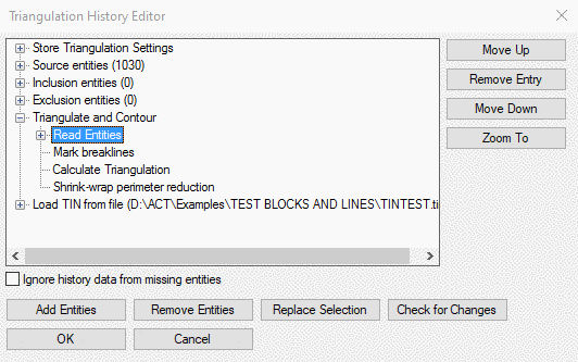
Move Up / Move Down moves the selected edit up or down in
the chronological list of edits.
Remove Entry removes an edit from the TIN.
Zoom To centers the CAD screen on the location of the
selected edit.
Ignore history data from missing entities If toggled OFF,
all history data in list will be used to process the TIN. If toggle
ON, any entities not available will not be used to recreate the
TIN, and therefore will be removed until the missing TIN entities
are restored.
Add/Remove Entities allows you to select new items to add
to the TIN or select existing items to remove from the TIN.
Replace Selection allows you to replace a TIN edit in the
history with a new edit.
Check for Changes will read the TIN file and check to see
if any changes have been made that are not currently reflected in
the current TIN file.
| Converted from CHM to HTML with chm2web Standard 2.85 (unicode) |