At the heart of nearly every land design project is at least one terrain model. These models go by several names and one of the most common is that of a "TIN" or Triangulated Irregular Network; another common name is that of a "DTM" or Digital Terrain Model. Since accurate representations of a surface model are significantly important to most land development projects, having a thorough understanding of the Triangulate & Contour controls is very important.
Surface models are generally comprised of combinations of the following general data types:
Carlson provides a programming interface for these file types and also offers a third file type (*.GRD) for the representation of terrain data. See the Notes section for additional details.
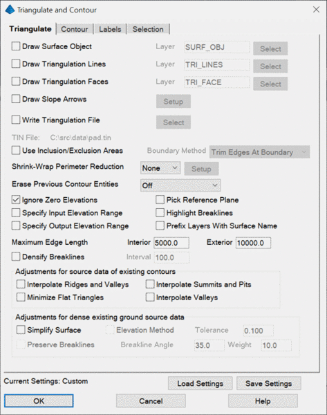
The Triangulate tab provides options and
settings that control the creation and analysis of the TIN
itself.
Draw Surface Object: This option
draws the triangulation faces as a Carlson Surface
Object.
Draw Triangulation Lines:
When enabled, the program will draw the
triangulation using simple line entities at the appropriate
elevation(s). Use the Select button or specify the
layer for these lines.
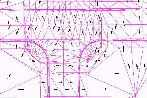
Draw Slope Arrows: When enabled, slope arrows are created within the triangles indicating the downhill dip direction as illustrated below.
Clicking the Setup button yields the Draw Slope Arrow Settings dialog box.
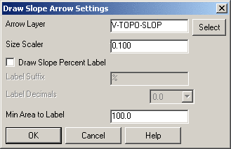
Arrow Layer: Indicate the layer to which the slope arrows are to be placed.
Size Scaler: Indicate a positive, non-zero value for the scale factor that should be applied to the slope arrows.
Draw Slope Percent Label: When enabled, the slope value (in percentage) of the triangle is labeled onto the slope arrow. Specify the desired unit suffix (e.g. "%") to apply to the end of the numerical value that is calculated from the TIN triangle(s).
Label Decimals: Indicate the amount of precision that is to be displayed on the slope label.
Min Area to Label: Indicate the smallest allowable triangle size that can be used for the slope percentage labels.
Write Triangulation File: When enabled (strongly suggested), an external surface model file is created which can subsequently be used for volume calculations, the creation of profiles, cross-sections and graded pads. Carlson currently provides two file types to store the DTM data created by the Triangulate & Contour routine:
Use Inclusion/Exclusion Areas:
When enabled, the program will prompt you for
inclusion and exclusion polylines and prevents the use of the
Shrink-Wrap Perimeter Reduction option.
These are used to further control the area of activity for
triangulation and contouring. The inclusion and exclusion polylines
must be closed polylines and when used, must be drawn before using
Triangulate & Contour. It is suggested that the height
of the Command: line display must be set
to show at least two lines so that the additional prompts can be
easily viewed. Refer to the Notes section for
additional information on Inclusion/Exclusion polyline
selections.
Boundary Method: This option
controls whether edges that cross the inclusion or exclusion
perimeter are trimmed or removed. Use the Remove option if you
don't want the triangulation to interpolate across the perimeters.
Use the Trim option if you want the triangulation to fill the area
up to the perimeter.
Shrink-Wrap Perimeter Reduction: This option produces an inferred Inclusion region around the data to be selected and mimics the results of the Shrinkwrap Entities command. Under the Setup, there is an option to draw the shrink-wrap perimeter polyline on a specified layer.
Ignore Zero Elevations: When enabled, this option will filter out all data points and entities at an elevation of zero from the triangulation data set.
Specify Input/Output Elevation Range: If you would like to manually set the range over which to contour, select either or both of the aforementioned toggles. One controls the triangulation of the source data and the other for the contour output. The program will automatically contour from the lowest elevation in the data set up to the highest at the increment specified in Contour Interval.
Prefix Layers With Surface
Name: This option applies when
using Write Triangulation File. The file name is added as a prefix
to all the layers created during Triangulate and Contour as a way
for layer management to organize all the contouring layers for a
surface file.
Max Triangle Length: Two bounds are provided to limit the length of the "legs" within a triangulation network. Based on the available data, if the edge length of a triangle exceeds the respective bound, the triangle will not be formed:
Densify
Breaklines: This option subdivides
linework segments for the input data so that the maximum length of
the segments is the specified Interval. This option is similar to
the Densify Polyline Vertices command except that the entities are
not modified in the drawing. Having shorter breakline segments is
often helpful for holding the breaklines in the TIN and making more
regularly sized triangles.
Minimize Flat Triangles: When enabled, this toggle instructs the triangulation "engine" to iterate through the triangulation permutations to minimize the occurrence of "flat" (or more precisely, horizontal) triangles. Flat triangles often occur when creating surface models from contour data. In this scenario, the often used Delaunay triangulation algorithm may produce unrealistic results. The Minimize Flat Triangle option will perform additional permutations of the triangulation network through the use of the Surface Manager > Swap Edge routine in an attempt to maximize the number of "sloped" triangles. Another option that produces similar results is the Interpolate Ridges and Valleys option.
Before: Surface made from an existing contour map with Minimize Flat Triangles disabled.
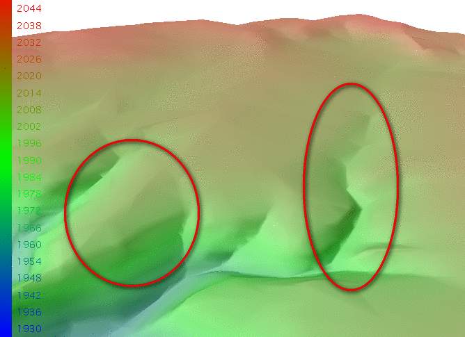
After: The same surface with Minimize Flat Triangles enabled. Note the better defined ravine and ridge definitions.
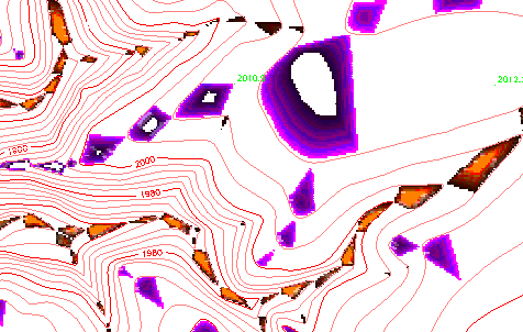
Difference: A Cut/Fill Color Map showing the regions of significant triangulation difference between the "Before" scenario and the "After" scenario of "Minimize Flat Triangles."
Erase Previous Contour Entities: In the event that a TIN needs to be recreated and Carlson-produced contours are in the drawing, three options exist that allow you to control whether or not the contour data should be removed from the drawing:
Pick Reference Plane: When enabled, this option allows you to contour an overhang or cliff by changing the reference plane to a side view. The reference plane can be specified by using the View>Viewpoint 3D>View command (see the AutoCAD/IntelliCAD Help menu for additional details) or by specifying three data points on the cliff (two along the bottom and one at the top).
Highlight Breaklines: When enabled, this routine highlights breaklines in the triangulation network by drawing the triangulation lines along breaklines in yellow.
Interpolate Ridges and Valleys: The purpose of this option is to avoid flat areas by better defining surface ridges and valleys. When enabled, this option inserts breaklines into the drawing which are subsequently used in the triangulation process in an attempt to minimize flat, horizontal triangles.
Interpolate Summits and Pits:
When enabled, this option creates additional
triangulation in a summit or pit situation to more accurately
represent existing ground conditions from a surface model created
from contour entities. Since the tops of hills and the bottom of
pits are often not shown on existing ground contour maps, this
option often helps improve the accuracy of existing terrain
conditions.
Interpolate Flow Paths: this function generates 3D data
polylines from a contour map that approximate the downhill flow of
water through valleys. These polylines are then used when creating
a triangulation and can improve the it in these valley regions by
giving more definition to these areas. The polylines are created by
looking for "sharp" or angled regions of the contours, and then
connecting these regions with a smooth curve.
Simplify Surface: When enabled, this option reduces the digital size of a surface without significantly compromising the integrity or accuracy of the surface itself. The most common application to enable this option is when using very large datasets, such as smoothed contours. Its use is less applicable to design surfaces or surfaces based on surveyed points, but it can still be utilized.
Elevation Method: When enabled, this option reduces the size of the surface file by analyzing the difference in elevation between each vertex of the TIN and the vertices directly surrounding it, assigning a numerical weight or value to each vertex. If it is determined that the calculated weight for a particular vertex is less than the Tolerance factor, the vertex is a candidate for removal. The number of vertices removed is directly proportional to the Tolerance factor, so the higher the Tolerance factor, the more vertices are removed and vice versa.
Preserve Breaklines: When enabled, this option analyzes the TIN by focusing on the edges; calculating the angular difference between adjacent triangular faces. If the angular difference between edges is greater than the specified Breakline Angle, it is considered to be a breakline, and it is preserved. If its angular difference is determined to be below the Breakline Angle, it becomes a candidate for removal. In that case, the Weight factor is applied to the corresponding vertex, adjusting its original value. If the resulting value is still below the Tolerance, it is then removed. The number of vertices removed is inversely proportional to the Weight factor, so the greater the Weight factor. The fewer vertices that are removed, the lower the Weight factor, the more vertices that are removed.
A good rule-of-thumb that can be used when deciding whether or not to use these options is:
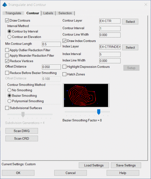
Draw Contours: When enabled, the program will draw contour lines using the designated settings after triangulation process is complete. Otherwise, only the designated Triangulation operations are performed. If this option is disabled and contours are subsequently desired, use the Contours from TIN File command.
Interval Method: Indicate the desired elevation(s) for contours to be drawn:
Contour Layer/Index Layer: Specify the layer to which the contours/index contours are to be drawn.
Contour Interval/Index Interval: Specify the interval to which the contours/index contours are to be drawn.
Contour Line Width/Index Line Width: Specify the line width to be applied to the contours/index contours.
Draw Index Contours: When enabled, index (or "major") contours will be created with independent characteristics from the regular contours.
Min Contour Length: Specify the minimum linear threshold that should be used to draw contours.
Apply Outlier Reduction Filter:
When enabled, this option attempts to remove
"the jaggies" which tend to occur along long, thin
triangles.
Apply Meander Reduction Filter: This
option smooths contours by removing back-tracking.
Reduce Vertices: When enabled, this option removes extra vertices from the contours using the Offset Distance value. The Offset Distance is the maximum amount that the polyline can move horizontally when removing a point. The result of this action is often a significant reduction in vertex locations along the contour resulting in a more efficiently-sized and compact drawing file.
Offset Distance: Specify the maximum allowable distance for shifting the original contour line in order to reduce vertices. The reduced contour will shift no more than this value, at any point, away from the original contour line. A lower value will decrease the number of vertices removed and keep the contour line closer to the original. A higher value will remove more vertices and allows the contour to shift further from the original location.
Reduce Before Bezier Smoothing: When enabled, this option removes extra vertices from the contours before they undergo Bezier Smoothing using the Offset Distance value. The Offset Distance is the maximum amount that the polyline can move horizontally when removing a point. Removing points before smoothing gives the Bezier smoothing more freedom to make the contour curvy.
Contour Smoothing Method: Indicate the desired amount of smoothing (often used for existing, natural ground conditions to simulate a "weathered terrain" effect) that should be applied to the contours:
Subdivisional Surfaces: When enabled, adjust the horizontal slider to indicate the degree of triangular subdivisions. This causes each triangle in the triangulation surface model to be subdivided into (x + 1)^2 triangles, where x = Subdivision Generations. The mathematically generated sub-triangle vertices are raised or lowered to provide smoother contours. More generations increase the smoothness of the contours but incur increased processing time. Although this algorithm does not produce "crossing contours," it can result in undesired contours in terrain scenarios such as where graded slopes abruptly transition to nearly horizontal slopes (e.g. the sides and bottom of a detention pond).
Bezier Smoothing Factor: Adjust the horizontal slider to obtain a preview of how much smoothing can be expected at each setting. Sliding the bar to the left results in a lower setting which have less looping or less freedom to curve between contour line points. Likewise, moving the slider to the right results in a setting that increases the looping effect. Note that too much smoothing applied in some situations can result in crossing contours.
Highlight Depression Contours: When enabled, use the Setup button to establish general configuration settings for depression contours.
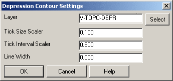
Layer: Specify the layer to which the depression contours are to be drawn.
Tick Size Scaler: Indicate the relative scale factor that should be applied to the depression ticks.
Tick Interval Scaler: Indicate the desired interval scaler which controls the spacing of the depression ticks.
Line Width: Specify the line width to be applied to the depression contours.
Hatch Zones: When enabled, this option will create hatching between the contours based on elevation zones. The following dialog will open allowing the user to specify the hatch type and color for each elevation zone. The entire elevation range of selected data is displayed under Current Values.
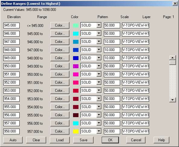
Auto: Opens the following dialog, allowing for automatic configuration of the range of elevations in each zone, assigning of colors and hatch patterns, and the scale.
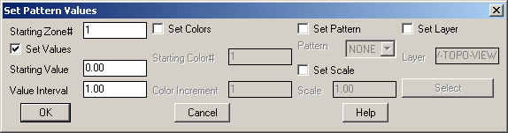
Starting Zone: Sets the zone with which to begin the application of the setting defined in this dialog. For Instance, if the Starting Zone was set to 10, the settings definitions applied here wouldn't affect Zones 1-9, but would start at Zone 10.
Set Values: Enables the Starting Value and Value Interval fields, which allow the user to specify the starting elevation for the given zone and set the zone increment.
Starting Value: Sets the elevation of the beginning zone to define.
Value Interval: Sets the elevation increment for subsequent zones.
Set Colors: Enables the Starting Color and Color Increment fields.
Starting Color: Sets the starting color number based on the standard CAD color chart.
Color Increment: Sets the color number to increase for subsequent zones. So if the increment was set to 5, and the starting color was 60, the next color would be 65, 70, and so on.
Set Pattern: Sets the hatch pattern for the defined zones.
Set Scale: Enables the Scale option.
Scale: Sets the scale for the selected hatch pattern.
Clear: Clears the all of the Elevation fields in the dialog.
Load: Loads previous settings from a saved .pat file.
Save: Saves the current setting configuration to a .pat file.
Scan DWG/Scan CRD : These buttons report the elevation
range which can help with choosing the contour interval.
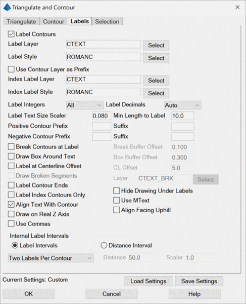
Label Contours: When enabled, contours will be labeled based on the settings below. If this option is disabled and further contour annotation is desired, utilize the Contour Elevation Label command.
Label Layer: Specify the layer name for intermediate contour labels. To
only label index contours, enable the Label
Index Contours Only option.
Label Style: Specify the text style that will be used for the contour label text.
Use Contour Layer as
Prefix: This option adds the
Contour Layer name to the Label Layer name.
Index Label Layer: Specify the layer name for index contour labels.
Index Label Style: Specify the text style that will be used for the index contour label text.
Label Integers controls
how many digits to label to the left of the decimal. For example,
if all contours are in the 5000's, then setting for three digits
would label the 5280 contour as 280.
Label Decimals: Specify the amount of precision to display on the contour labels.
Label Text Size Scaler: Specify a relative text size scale factor to be applied to the label(s).
Use Commas adds a comma
into the labels for the thousands place such as "5,000" instead of
"5000".
Min Length to Label: Specify the desired minimum length of contours that should be annotated. In other words, Contours whose length is less than the value will not be labeled.
Positive/Negative Contour Prefix: Indicate a desired string of prefix text (e.g. Elev= ) that is to precede the positive and/or negative contour elevations, respectively.
Positive/Negative Contour Suffix: Indicate a desired string of suffix text that is to follow the positive and/or negative contour elevations, respectively.
Break Contours at Label: When enabled, the contour lines will be broken and trimmed at the label location for label visibility. As an alternative to physically placing a gap into the contour, consider using the Hide Drawing Under Labels option.
Break Buffer Offset: Specify the offset distance which determines the gap between the end of the trimmed contour line and the beginning or ending of the text.
Draw Box Around Text: When enabled, a rectangle is drawn around the contour elevation labels.
Box Buffer Offset: Specify the offset distance which determines the gap between the box and the beginning or ending of the text.
Label At Centerline Offset: When creating contours and subsequent plan sheets for roads, enable this option to position the labels at a fixed offset from a centerline. The program automatically uses any polylines in the drawing that are tagged as centerlines. To check whether a polyline is a centerline, use the Centerline ID command. To create a centerline polyline from a centerline file, use the Draw Centerline File command.
Draw Broken Segments: When enabled, the segments of contours that have been broken out for label visibility will be redrawn as independent segments. To join these segments back into the contour, use the Join Nearest command.
Layer: Specify the layer that is to receive the newly drawn broken segments.
Label Contour Ends: When enabled, the ends of "open" contours will be labeled.
Label Index Contours Only: When enabled, only the index contours are labeled. This option is active only when Draw Index Contours has been selected in the Contour tab.
Hide Drawing Under Labels: When enabled, a "Wipeout" entity is placed with the annotation label that will create the appearance of trimmed segments at the contour label, even though the contour line is still fully intact. This feature provides the user with the best of both worlds; you have clean looking contour labels yet the contour lines themselves remain contiguous. This feature will also hide other entities that are in the immediate vicinity of the contour label.
Align Text with Contour: When enabled, the contour elevation labels will be rotated to align with their respective contour lines.
Use MText: When enabled, contour labels are created using the MText entity type. Otherwise, the standard DText entity type is used.
Draw On Real Z Axis: When enabled, the contour labels are placed at the same "Z" (elevation) value of the contour itself. When disabled, the contour labels are placed at a "Z" (elevation) value of 0 (zero).
Align Facing Uphill: When enabled, the contour elevation labels will still be rotated to align with their respective contour lines, but the labels will be placed in such a manner that the top of the text label will always be toward the uphill side of the contour.
Internal Label Intervals: Indicate the desired method for contour labels within the contour itself:
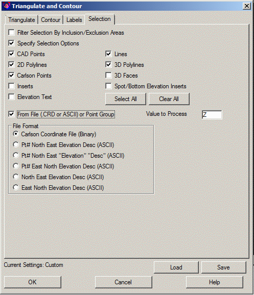
Filter Selection By
Inclusion/Exclusion Areas: This option filters out selected
entities from the triangulation that are outside the surface area
defined by the inclusion/exclusion perimeter polylines. Otherwise,
all the selected entities are used for triangulation and then the
triangulation is trimmed at the inclusion/exclusion perimeters.
Whether to prompt for inclusion/exclusion perimeters is specified
on the Triangulate Tab.
Specify Selection Options: When enabled, indicate the type(s) of entities that are to be used during the triangulation process. This is an excellent method of "filtering out" unwanted entity types or enabling the use of desired entity types.
CAD Points, Lines, 2D Polylines, 3D Polylines, 3DFaces, Elevation Text and Inserts (blocks) are standard CAD entities types.
Carlson Point Inserts refer to Carlson points (such as those placed with the Draw Field to Finish command or which utilize the Carlson "SRVPNO*" family of blocks with point number, elevation, and description attributes).
Spot/Bottom Elevation Inserts include text entities that start with 'X'.
From File: When enabled, allows you to triangulate from the points in an external coordinate (.CRD) or ASCII file. This option also provides access to the use of Point Groups as a data source.
An Error Log is generated if the triangulation routine finds vertical conflicts between breaklines or other surface entities and displays the conflicts in a "docked dialog box." Three types of conflicts are reported (each conflict type is listed into its own category):
Click the "+" sign beside a category to display the individual conflicts within that category and click the "-" sign to collapse the list. When a line item error is selected, a highlighted arrow is temporarily placed in the drawing to indicate the exact location of the specific conflict. Zoom functionality allows the user to more closely inspect the specific problem area, and if needed a marker can be drawn or a report generated for an individual conflict or conflicts.
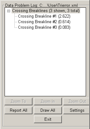
Zoom To: Centers the display on the location of the error without affecting the zoom resolution.
Zoom In: Increases the ability to see detail.
Zoom Out: Decreases the ability to see detail.
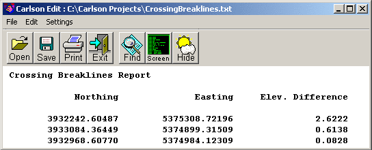
Report One/All: This option toggles between "One" and "All" depending whether a single line item conflict or an entire category is selected from the error log. An error report is generated listing the x-y position and the elevation difference of the entities in conflict.
Draw One/All: This option toggles between One and All depending whether a single conflict or a category is selected from the list. This option draws an "X" symbol at each selected conflict.
Settings: Indicate the desired configuration settings for the error log:
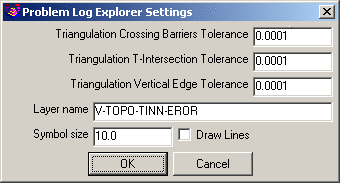
Tolerances: Indicate the lowest elevation difference threshold that should be reported for Crossing Breaklines, Vertical Edges and Breakline T-Intersections, respectively.
Layer Name: Specify the layer name for the "X" entities drawn with Draw One/All option. This also sets the layer name for the Draw Lines option.
In the case of crossing polylines, Draw Lines will trace over the polylines responsible for the conflict.
Symbol Size: Specify the size of the "X" symbol that is drawn to delineate the selected errors. This will determine the actual size of the symbol in the drawing. This value is not multiplied by the horizontal drawing scale.
The following are the most often encountered prompts:
Select the Inclusion perimeter polylines or
ENTER for none.
Select entities: Select the desired closed polylines that form the bounding
inclusion area(s) of the surface model and press Enter when
complete.
Select the Exclusion perimeter polylines or
ENTER for none.
Select entities: Select the desired closed polylines that form the
regions(s) of the surface model where triangulation should not
occur and press Enter when complete.
Select the points and breaklines to
Triangulate.
Select entities: Select the desired entities from CAD using standard CAD
selection methods and press Enter when complete.
Pulldown Menu Location(s): Surface (Survey, Civil, Hydro,
Construction, Field, Natural Regrade), Takeoff > Surface
Tools
Keyboard Command: tri
Prerequisite: 3D entities in the drawing (defined by the
Selection Tab) and/or an external point
file
| Converted from CHM to HTML with chm2web Standard 2.85 (unicode) |