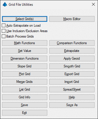
Grid File Utilities
This command is used to modify and create grid files. The
modifications can be done manually on a single grid, on multiple
grids in a batch mode, or saved and rerun using the grid macros
created with the macro editor. To modify manually, start by picking
the Select Grid(s) button. There is an option to use inclusion and
exclusion polylines to only modify the grid within/outside these
perimeters. With this option active, the program will prompt for
inclusion and exclusion polylines when a function is selected. Only
grid cells inside the inclusion polylines will be modified. Grid
cells inside the exclusion polylines will not be modified. If no
inclusion and exclusion polylines are selected, then the entire
grid will be modified. Each function is described below.
- Select Grid(s): This is
the first step to load a grid. Usually a grid needs to be loaded
before running a function. If Batch Process Grids is turned on,
then multiple grids may be selected while holding down the Shift or
CTRL buttons.
- Auto Extrapolate On
Load: This will extrapolate values for any null or empty
values in the grid as the grid is loaded.
- Use Inclusion/Exclusion
Areas: If this is turned on, then the GFU function will only
be applied within the selected inclusion polyline and outside the
selected exclusion polyline.
- Batch Process Grids:
When this option is turned on, GFU functions can be executed on
many grids at once. It is recommended to move the grids to a backup
directory, or create a copy of them, as the grids are over-written
with the same name. The functions that cannot be batched are: Plot
Grid, Merge Grid, List Grid, Import Grid, and Spreadsheet.
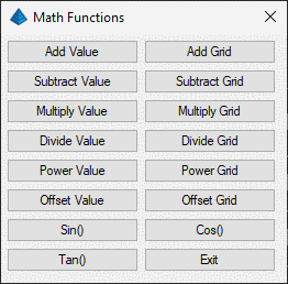
- Add Value: Adds an
entered value to the grid values. (GridA + X)
- Add Grid: Adds one grid
to another grid. (GridA + GridB)
- Subtract Value:
Subtracts an entered value from the grid values. (GridA - X)
- Subtract Grid:
Subtracts one grid from another grid. (GridA - GridB)
- Multiply Value:
Multiplies the grid values by an entered value. (GridA * X)
- Multiply Grid:
Multiplies the grid values by another grid. (GridA * GridB)
- Divide Value: Divides
the grid values by an entered value. (GridA / X)
- Divide Grid: Divides
the grid values by another grid. (GridA / GridB)
- Power Value: Raises the
grid values to the specified power. (GridA ^ X)
- Power Grid: Raises the
grid values to another grid for the "power". (GridA ^ GridB)
- Offset Value: Offsets the grid elevations perpendicular
to the grid surface. Use a negative value to offset down.
- Tan(), Sin() and Cos():
Applies these functions to the grid values which need to be in
decimal degrees. (tan(GridA), sin(GridA), cos(GridA))
- Max Value: Compares a
grid and a value and takes the Maximum value of either. This is a
way to stop a grid from going negative, below zero.
- Max Grids: Compares a
grid with another grid and takes the Maximum (higher) value of
either.
- Min Value: Compares a
grid and a value and takes the Minimum value of either. This is a
good way to cap a grid off at a certain value so it never goes
higher than the specified value.
- Min Grids: Compares a
grid with another grid and takes the Minimum (lesser) value of
either.
- Less Value: Asks for a
value to compare and a value to assign and uses the following
logic:
If GridA < compare_value then GridA = assign_value, otherwise no
change
- Less Grids: Asks for a
grid to compare and a grid to assign and uses the following
logic:
If GridA < compare_GridB then GridA = GridC, otherwise no
change
- Greater Value: Asks for
a value to compare and a value to assign and uses the following
logic:
If GridA > compare_value then GridA = assign_value, otherwise no
change
- Greater Grids: Asks for
a grid to compare and a grid to assign and uses the following
logic:
If GridA > compare_GridB then GridA = GridC, otherwise no
change
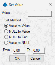
- Set Value: assigns the
grid elevations to the user-specified value. Using inclusion and
exclusion perimeters are usually required for this command. For
example by using Set Value with the inclusion perimeter option, you
could set the grid values to 0.0 within the inclusion polyline for
a strata thickness grid. The four options are:
-
- Value to Value will set all values to one value
- Null to Value will set all Nulls to one value
- Null to Grid will set all Nulls to another specified
grid
- Value to Null will set all values to Null.
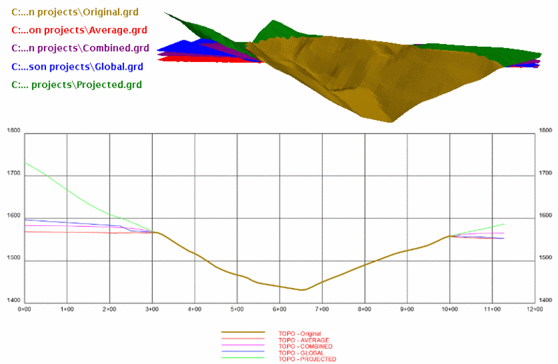
- Extrapolate: This
function will assign values to null grid nodes by one of four
methods.
Global Trend finds the average slope and slope direction from the
existing grid elevations and applies this slope to calculate the
missing elevations.
Average method calculates a grid elevation as the average of its
nearest neighbors. This will create a very flat extrapolation.
Projected method extends the trend at the edge (as opposed to
finding an average slope of the entire surface like the Global
option).
Combined method uses a combination of both the Average and
Projected methods.
An example extrapolation of a surface using each method is shown
below in 3D and in a profile view. The Original surface (brown
color) is an example valley that only contains data in the center
of the grid.
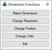
- Match Dimensions: Sets
the grid position and resolution to match another grid file. The
program will prompt for a grid file to get the position from.
Certain commands require grids match position and resolution.
Running this command will ensure grids will match.
- Change Position: This
lets you change the lower left and upper right corners of the grid
file. For example, you can use this routine to localize a grid file
if you have a large grid for the entire site but are currently
working on a smaller area. If the new position covers area outside
the original position, any grid cells in this area will be assigned
a null value. Otherwise the program uses the original grid values
for the new grid position.
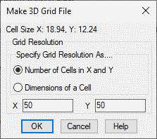
- Change Resolution: This
changes the grid resolution (number or dimensions of grid cells).
The program uses the original grid values for calculating the grid
values at the new resolution. Enter a new value for X and Y number
of cells or dimensions of cells.
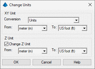
- Change Units: Scales
the grid X/Y and/or Z values to switch units such as meters to
feet.
- Apply Geoid: Adjusts the grid elevations by the selected
geoid. To use this function, the grid projection must be defined in
the Settings > Drawing Setup command.
- Slope Grid: Converts a grid of elevations to a grid of
slope values.
- Smooth Grid: This
function has three smoothing method. The Least-Squares method
applies a moving least-squares algorithm to adjust the grid
elevations. The Eliminate Spikes method adjusts grid nodes with
elevations too different from neighbors within the search radius.
Quadratic smoothing uses neighboring nodes to adjust each grid
node. This routine can be used to refine a grid so that the
contours from the Contour from Grid routine appear smoother.
Typically this adjustment is relatively small. To get more
smoothing, run the routine more times.
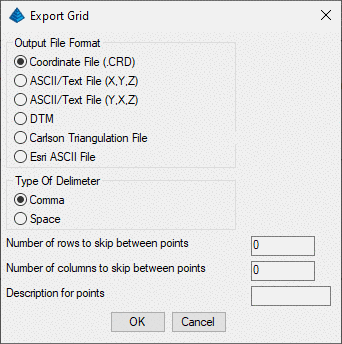
- Export Grid: There are
several choices for export options: Carlson Coordinate File (CRD),
ASCII text as XYZ, ASCII text as YXZ, DTM, Carlson Triangulation
(TIN) and Esri (ASC). There are two options for the ASCII
delimiter, either a comma or a space. There is an option to skip a
number of rows and columns between the exported points. When
exporting into the Carlson CRD file, the description for the points
is set at the bottom.
Export to DTM writes the current grid file to a DTM format text
file. The format of this file is the following:
DTM 1.0
Header Line
test.dtm
Name of file
51
Number of cells in X direction
51
Number of cells in Y direction
79442.4697 Lower left
grid corner Y coordinate
14899.0326 Lower left
grid corner X coordinate
0.0
Lower left grid corner Z coordinate
11.5618
Dimension of cell in X direction
7.0639
Dimension of cell in Y direction
1581.2612 Grid
cell values starting from lower left, moving from left to right
1580.8879
1580.3257
etc...
- Merge Grids: creates a
grid file by merging together two existing grid files, grid1 and
grid2. The current grid is grid1 and the program will prompt for a
second grid. These two grids must overlap with the same location
and resolution. The inclusion and exclusion perimeters apply to
grid2 such that the merged grid will consist of grid2 cells within
the inclusion perimeters and outside the exclusion perimeters and
grid1 cells everywhere else. The result is stored in the current
grid.
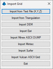
- Import Grid: There are
several formats that may be imported.
-
- Text File (ASCII): This function allows for various formats.
The data can be comma or space separated or in fixed width
columns.
- Carlson Triangulation (TIN, FLT)
- DEM (Digital Elevation Model) such as from the USGS (US
Geological Survey)
- Esri (ADF)
- Minex ASCII DUMP (ASC, CSV)
- Mintec
- Surfer (GRD both ASCII and Binary)
- Vulcan ASCII Grid (ASC, CSV)
Import from Text File
(X, Y, Z) creates a grid file from X Y Z data in any text
file. There does not need to be a current grid file loaded since
this routine will create a grid file. The text file should consist
of one X Y Z coordinate per row with the first coordinate being the
lower left grid corner and the last coordinate as the upper right
grid corner. There are options for space or comma separated
coordinates and for the order of the coordinates as either row
(left to right) or column (bottom to top). The prompting will be as
follows:
Separation type [<Space>/Comma/FixedWidth]?
Column number for X coordinate <1>:
Column number for Y coordinate <2>:
Column number for Z value <3>:
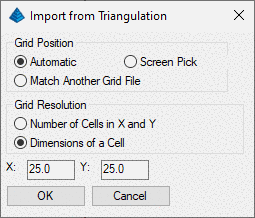
Import from
Triangulation prompts user to select a tin or flt file and
allows user to adjust grid position and resolution. The grid file
is created with the same name in the same directory as the selected
tin/flt file.
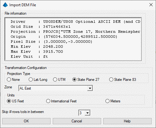
Import DEM/ESRI
prompts the user to select a DEM, ADF, or ASCII ESRI grid file to
be imported. The ESRI grid files can be created from ArcMap using
the Raster To ASCII tool. If the file format is recognized, the
program reads, and displays information about the source projection
of the DEM/ADF/ESRI file, and allows the user to define a target
projection for transforming the grid to a local coordinate system.
The "Skip every # rows/cols" option allows the user to reduce the
size of the imported grid file. In the case of a DEM/ESRI files
each pixel of elevation information of the DEM/ADF image data is
interpreted as representing an elevated point located in the center
of that pixel (not multiple points located on the edges of that
pixel). In contrast, the "Import DEM/ADF File Dialog" will output
the "Origin" of the DEM/ADF file in terms of the raster pixel
extents. The output grid file is created with the same name in the
same directory as selected DEM/ADF/ESRI file.
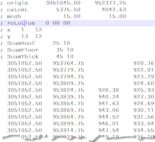
Import Minex ASCII DUMP allows user to import
multiple Minex ASCII grids from a single .asc or .csv file. The
imported grids will be automatically named according to the header
information in the .asc/.csv file. An example File Format is
provided below.
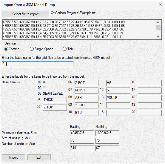
Import Mintec
allows user to import Mintec
GSM Model Dump as grd
files. User is prompted to select GSM Model Dump (txt) file, which
is then processed to determine minimum northing, easting (lower
left corner), resolution and size of the grid. First three columns
of the GSM model dump must represent the X, Y and SEAM LEVEL
respectively, a base name for the grid files is specified along
with name of the quality that each column represents. User can
define up to 17 qualities. When the import button is pressed all
the imported grids are created with the name "BASE NAME-SEAM
LEVEL-BASE ITEM.grd" in the same directory as source dump
file.
Import Surfer prompts
to select a grd file from Surfer program and creates a grd
file.
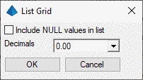
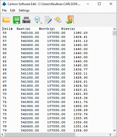
- List Grid: displays a
list of the northing, easting and elevation of each grid corner.
There is an option to Include NULL values in the list. A grid node
will have no value, or a Null value (listed as None) if the grid
node was outside the limits of the data during Make 3D Grid
File.
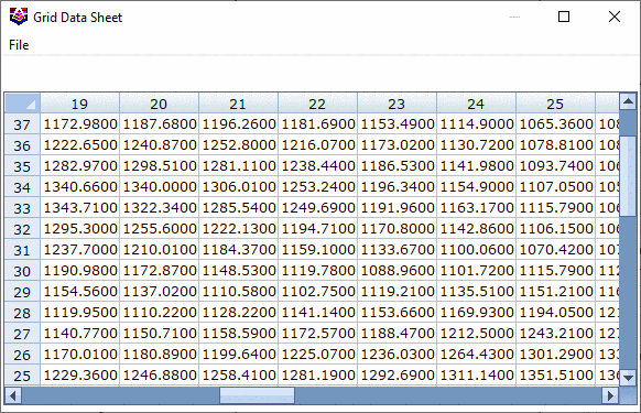
- Spreadsheet: displays
the grid elevations in a row and column spreadsheet that is in the
same layout as the grid file. Grid elevations can be edited in this
spreadsheet and saved upon exiting the spreadsheet.
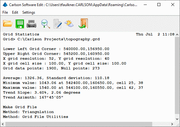
- Grid Info: This
function displays information about the grid file. It is a form of
Grid Statistics. The items it displays are shown in the report
below:
Macro Editor: The Macro
Command Recorder allows you to create a script for grid
modification and save these steps to a .gfu file. These macros can
be rerun to repeat grid modifications when the source grids are
modified, thus saving time on tedious manipulation. Macros can also
be reviewed for accuracy, whereas manual manipulation of grid files
cannot be checked with as much detail. When writing a macro, you
essentially perform the normal grid manipulations using the
functions on the left of the dialog. Although the prompts will be
slightly different than manual manipulation, the steps will be
automatically added to the text window. You can then copy/paste the
text as needed to speed up the macro-writing process.
Quick notes on the macro editor:
- You may enter the script manually (typing each variable,
function, etc), or you may use the function buttons on the left.
Some functions are more easily written manually compared to using
the function dialogs on the left.
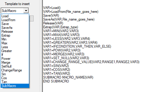
- Function templates may be inserted using the "Template to
Insert" droplist on the left. Using these templates, you can see an
example of the syntax for each function.
- You may add comments to the script to allow for easier review.
Comments are simply preceded by a semi-colon (;). With the
exception of the PERIM, INCLU, and EXCLU functions, any text
following a semi-colon will be seen as a comment (the program will
not attempt to read it upon execution of the script)
- Most all function follow a syntax of RESULT=FUNCTION. For
example, to evaluate the result of adding Grids A and B together to
create Grid C, the function would be written as C=A+B.
- When a variable is first defined, the variable will take on the
grid dimensions (cell size and lateral extent) of the right side of
the equal sign. For Example, consider an exmaple in which variable
A is defined as a grid and B is not yet defined. If you write the
equation B = A + 5, then variable B will cover the same lateral
extent and will use the same grid cell size as variable A.
If two grid variables do not use the same grid dimensions, they can
still be compared (note that this is not possible with manual
manipulation of the grids). For example, if Grid A and Grid B cover
only partially overlap, the equation B = A + 5 will allow Grid B to
retain it's original dimensions, but it will only be updated where
it overlaps A. In this way, you can avoid the intermediate step of
settings grids to the same location/cell size in order to compare
them.
- When using the functions on the left side of the dialog (Math
Functions, Comparison Functions, etc), you will sometimes be able
to select existing grid variables from a dropdown list. In order
for this list to be populated with the existing grid variables, you
must first Start the macro, otherwise the program will not display
the existing grid variables.
- When adding a step that involves another grid file, there are
three options for storing this grid into the script. Use Grid
Variable will use the grid assigned to the Grid Variable Name.
Prompt for Grid File Name will bring up a grid file selection
dialog each time the macro is run. Store the Grid File Name will
save the specific grid file name into the macro.
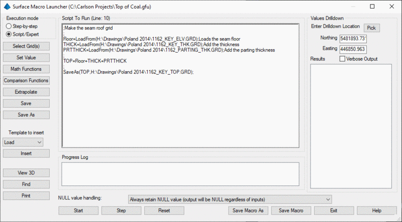
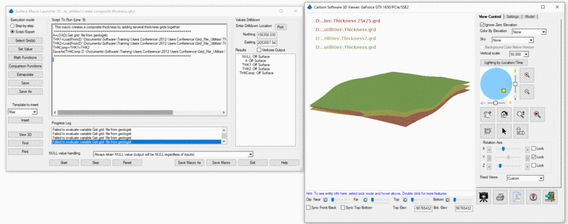
Surface Macro Launcher
Details
The Surface Macro Launcher displays the GFU file name in the upper
menu bar. This is an editor, and you can use basic functions like
CTRL-X, CTRL-C & CTRL-V for cut, copy, & paste. GFU files
also can be edited easily in any text editor, such as Notepad,
WordPad or K-Edit. If there are any errors in the GFU during its
execution, they will be displayed in the error log section when the
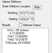
macro runs. The Values Drilldown on the right side of the dialog
allows you to inspect the calculations/grid variables at an actual
Northing-Easting location, which is especially useful for checking
that the results are correct. You may screen-pick a location by
clicking the Pick button, or you may manually enter the Northing
and Easting coordinates. As the macro runs, each variable will be
display in the text readout below these options. If the Verbose
Output option is disabled, only a summary of the grid variables
will be displayed, with each variable updating as the macro runs.
If the Verbose Output option is enabled, the results from each line
of the macro will be displayed in the text readout.
- Step-by-Step: This execution mode is a simpler method
and is intended to be executed immediately. It is similar to the
previous windows simple "button pushing" to execute a function.
These two modes have completely different dialogs when the
functions are selected.
- Script/Expert: This mode stores the history and is a
replayable history of the operations. It contains all of the higher
level features and options, and is for the users who want to
program it manually.
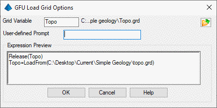
- Select Grids: In the Step-byStep mode, the File Open
dialog appears to select the file. In Script/Expert mode, the
following dialog initially appears to add the expression to the
macro for replaying. This function releases a variable if it is
previously defined, and loads a grid file and assigns a variable to
it. Another option is to enter an User-defined Prompt instructing
the user on which grid to select at the time the macro is run. The
dialog appears as shown. The preview shows how it will look when
inserted into the macro.
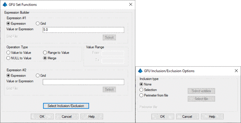
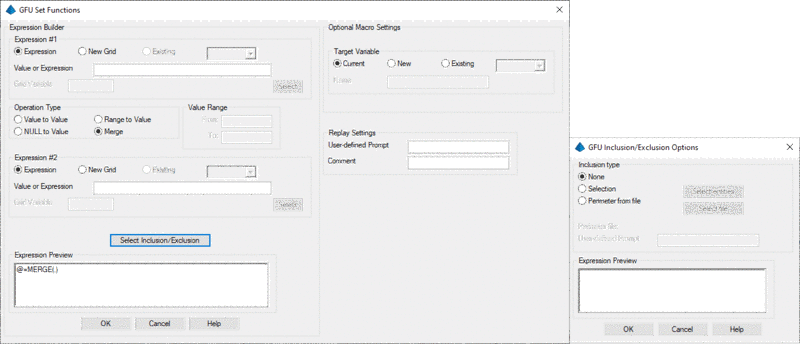
- Set Value: This function sets the grid to new values
based on the selected options. The Step-by-Step method has the
following Set Functions shown in the first image below. The Expert
method functions are shown in the second image. The expression #1
can either be set to a Value/Expression or to a New Grid file. The
operation type contains four options of Set Value.
Value to Value (A=B for each point of A, sets the value to the
value of B, Expr#1))
Null to Value (C=SET_NULL (A,B), For each point of C, sets the
value to the value of A (Expr#1) if defined and the value of B
(Expr#2) otherwise)
Range to Value (A=CHANGE_RANGE(B,C,D,E), for each point of A, if
value of B (Expr#1) is between C and D, sets the value to value of
E (Expr#2) or Null if not specified)
Merge (C=MERGE(A,B), for each point of C, sets the value to the
value of B (Expr#2) if defined and the value of A (Expr#1)
otherwise). Expression#2 is what the value will be set to, or to a
new grid.
The Select Inclusion/Exclusion options can be set to None,
Selection (manually select polyline), or a PLN polyline file. Note
that PLN files may be created with the
Export Polyline File command. The preview of the expression
appears in the expert mode. These two modes appear the same in all
the various functions. To set a grid to NULL, where the values fall
within a range, use the following format:
A=CHANGE_RANGE_VALUE(A,lowrange,highrange,NULL)
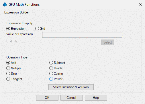
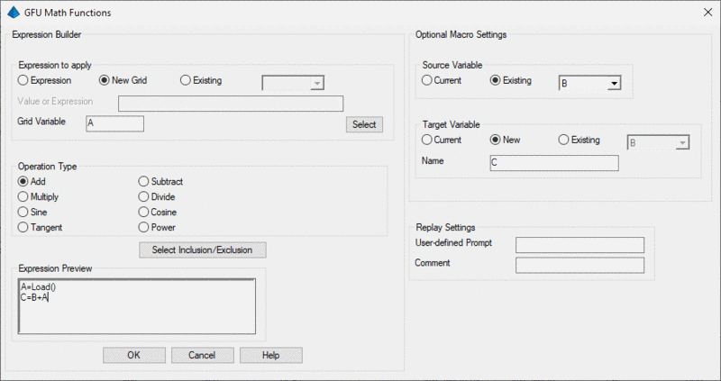
- Math Functions: These functions apply the mathematical
operations selected to the loaded grid. The Step-by-Step mode
dialog is shown first, followed by the Script/Expert mode. The
operations are Add, Subtract, Multiply, Divide, Sine, Cosine, and
Power function.
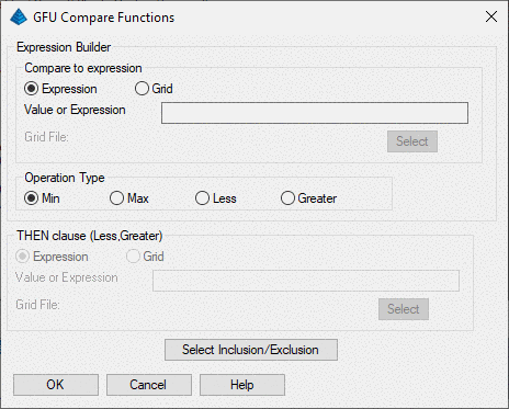
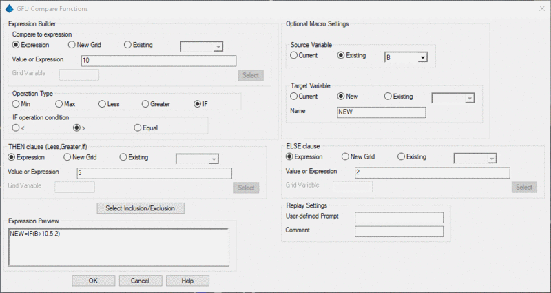
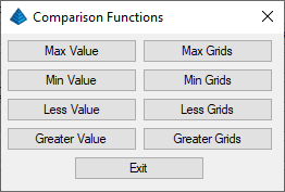
- Comparison Functions: The Step-by-Step mode uses the
Min, Max, Less, and Greater commands for grid editing. This is
shown below in the first dialog. The second one shows the
Script/Expert dialog that also contains the If Statement functions.
The IF statement is the standard format of IF This, Then This, Else
This. The Preview shows how it will appear in the GFU
syntax.
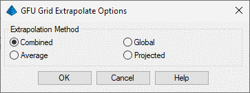
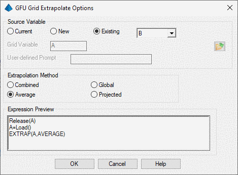
- Extrapolate: This function uses the four methods
described above to extrapolate the grid to fill in any Null values.
Details on each extrapolation method are provided above.
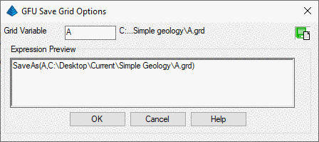
- Save/Save As: These commands add the syntax of saving to
the macro. The variable can be the existing, or set to a new one
here.
- Template to insert: This option allows for easy
insertion of the syntax for the following functions.
- Nested Submacros: It is possible to define a macro for a
certain function, and then call that macro and apply it to other
variables in either the same macro, or in a different macro. Here
are 3 examples of Submacros.
Submacro in the same macro that calls it. There are two
submacros defined at the top, and then they are both called at the
bottom, THICK2 and THICK.
SUBMACRO THICK()
A1=LOADFROM($PROJECTPATH\one.grd)
B1=LOADFROM($PROJECTPATH\two.grd)
C1=A1+B1;
SAVEAS(C1,$PROJECTPATH\three.grd)
END SUBMACRO
;---------------------------------------------
SUBMACRO THICK2(A,B,D)
C=A+B;
SAVEAS(C,D);
END SUBMACRO
;---------------------------------------------
A1=LOADFROM($PROJECTPATH\one.grd);
B1=LOADFROM($PROJECTPATH\two.grd);
THICK2(a1,B1,$PROJECTPATH\three_b.grd);
THICK()
---------------------------------------------------------------------------------
Submacro in a different macro that calls it. The first
step is to define the submacros in their own gfu, this one contains
THICK and THICK2 and is saved as mymacros.gfu.
SUBMACRO THICK()
A1=LOADFROM(C:\downloads\one.grd);
B1=LOADFROM(C:\downloads\two.grd);
C1=A1+B1;
SAVEAS(C1,C:\downloads\three.grd);
END SUBMACRO;
;--------------------------------------
SUBMACRO THICK2(A,B,D)
C=A+B;
SAVEAS(C,D);
END SUBMACRO;
---------------------------------------------------------------------------------
INCLUDE: To include a previously defined macro in another
macro, the INCLUDE function is used. Once mymacros.gfu is created,
then it can be loaded (with INCLUDE) and referenced in another,
separate GFU macro.
INCLUDE($PROJECTPATH\mymacros.gfu);
A1=LOADFROM($PROJECTPATH\one.grd);
B1=LOADFROM($PROJECTPATH\two.grd);
THICK2(a1,B1,$PROJECTPATH\three_b.grd);
THICK();
Here is an example, with comments, where the bottom elevation
and the thickness are added together to get the roof, for 6 seams.
The Submacro is defined by the equation just once. Then it is
called and used 6 times at the bottom of the macro.
;Add the Floor and Thickness to get the seam Roof.
;Coal seams to apply this to are: C1,C2,C3,C4,C5,C6
;------------------------------------------------------
;LOAD THE GRIDS INTO MEMORY
;
C1_KEY_ELV=LOADFROM(C:\Carlson Projects\C1_KEY_ELV.GRD)
C1_KEY_THK=LOADFROM(C:\Carlson Projects\C1_KEY_THK.GRD)
C2_KEY_ELV=LOADFROM(C:\Carlson Projects\C2_KEY_ELV.GRD)
C2_KEY_THK=LOADFROM(C:\Carlson Projects\C2_KEY_THK.GRD)
C3_KEY_ELV=LOADFROM(C:\Carlson Projects\C3_KEY_ELV.GRD)
C3_KEY_THK=LOADFROM(C:\Carlson Projects\C3_KEY_THK.GRD)
C4_KEY_ELV=LOADFROM(C:\Carlson Projects\C4_KEY_ELV.GRD)
C4_KEY_THK=LOADFROM(C:\Carlson Projects\C4_KEY_THK.GRD)
C5_KEY_ELV=LOADFROM(C:\Carlson Projects\C5_KEY_ELV.GRD)
C5_KEY_THK=LOADFROM(C:\Carlson Projects\C5_KEY_THK.GRD)
C6_KEY_ELV=LOADFROM(C:\Carlson Projects\C6_KEY_ELV.GRD)
C6_KEY_THK=LOADFROM(C:\Carlson Projects\C6_KEY_THK.GRD)
;------------------------------------------------------
;DEFINE THE SUBMACRO EQUATION
;
SUBMACRO ROOF(X,Y,Z)
TOP=X+Y
SAVEAS(TOP,Z)
END SUBMACRO
;
;------------------------------------------------------
ROOF(C1_KEY_ELV,C1_KEY_THK,C:\Carlson Projects\C1_KEY_TOP.grd)
ROOF(C2_KEY_ELV,C2_KEY_THK,C:\Carlson Projects\C2_KEY_TOP.grd)
ROOF(C3_KEY_ELV,C3_KEY_THK,C:\Carlson Projects\C3_KEY_TOP.grd)
ROOF(C4_KEY_ELV,C4_KEY_THK,C:\Carlson Projects\C4_KEY_TOP.grd)
ROOF(C5_KEY_ELV,C5_KEY_THK,C:\Carlson Projects\C5_KEY_TOP.grd)
ROOF(C6_KEY_ELV,C6_KEY_THK,C:\Carlson Projects\C6_KEY_TOP.grd)
- View 3D: Using this option brings up the 3D Surface
Viewer that steps through live all of the grids and displays them
in 3D. This can be left open and moved to the side, or to another
monitor to see all the surfaces and how they are modified, in a 3D
view.
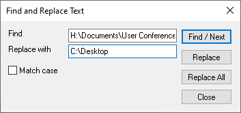
- Find: This is a Find, or Find and Replace to search the
GFU text and make edits. It is useful if a file path has changed
and all need to be reset to somewhere else.
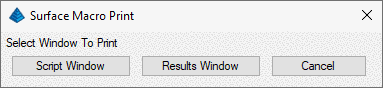
- Print: There are two options for printing. The Script
Window prints out the entire GFU syntax. The Results Window prints
out
- NULL Value Handling: This option determines how null
values will be handled in the grid calculations. The "Always retain
NULL Value (output will be NULL Regardless of inputs)" option will
force any calculations with NULL inputs to create a NULL output.
The "Treat NULL as 0.0 if one or more inputs are non-NULL; Retain
NULL if all inputs are NULL)" option will replace null values with
zeros for calculations, but will retain null values in the output
if all inputs are null.
- Start/Step/Reset: These buttons allow for individual
stepping through the macro. It will advance only one line at a time
with the Step. Start will run the entire macro. Reset will begin
back at the beginning.
- Save Macro As/Save Macro: This saves the GFU macro
either as its original name, or as a new name with Save
As.
- Values Drilldown: The Values Drilldown is a good method
for error checking on the macro. Use the Pick button to select a
spot in plan view to fill in the Northing and Easting boxes. Then
when the GFU is executed, the results of each line will be
displayed. The Verbose Output will show the value of each line L1,
L2, etc., instead of overwriting the variable each time it is
encountered.
Variables
Variables in the GFU can be any keywords providing meaningful
identification of the data loaded. A variable can be either just a
value or constant; or most commonly a surface (Grid or TIN).
Individual macro lines typically have one of the following
forms:
Variable1=Variable2
Variable1=Expression
Variable1=Function(Expression1,Expression2)
Whenever new variable name is encountered on the left side of the
equation, the new variable will be created. The program will use
its knowledge of the right side of equation to define a type of the
new variable. For example:
A=1.0
Variable A
will be just a value
A=LoadFrom(abc.grd)
Variable A is a grid loaded from file
B=A
Variable B is same variable type as A
B=(1+C+A)/D
Variable B will be 1+C+A, all divided by D. C
and D will need to be defined somewhere before this line in the
GFU.
Important!: Once a variable is defined, its type (like grid
location and resolution) does not change. Therefore, for the
existing variable A, the following expression:
A=Min(B,C)
is interpreted in the following way: for every point of the
existing surface A calculate values of surface B and C and use the
smaller of the two values to set new value of point elevation on
surface A.
The following operators may be used in the expressions:
+, -, *, / - regular arithmetic operators
<, >, =, ! (not) - logic operators
| (or), & (and) - binary operators
Changing the scope of the
equation
The scope of any line of the script can be modified by adding one
of the following inclusion/exclusion operators:
A=Min(B,C);INCLU()
- will prompt for inclusion at run-time
A=Min(B,C);INCLU(handle_here) - will
use AutoCAD entity with specified handle for the inclusion
A=Min(B,C);EXCLU() - will prompt for
exclusion at run-time
A=Min(B,C);EXCLU(handle_here) - will
use AutoCAD entity with specified handle for the exclusion
A=Min(B,C);PERIM() - will prompt for
polyline file with inclusions/exclusions
A=Min(B,C);PERIM(file_name) - will
use specified file with inclusions/exclusions
Multiple inclusions or exclusions can be appended in this manner.
Only points of target surface (A) passing inclusion/exclusion
filter will be evaluated.
For custom, user define prompting, the following text should be
used:
PERIM(,Prompt goes here) for user defined
interactive inclusion and exclusion selection in CAD
PERIM(*,Prompt goes here) for file selection
dialog with user defined prompts to select a PLN file.
The following script
functions are currently defined:
Macro functions (performing operations on the entire surface at
once)
LOAD() Prompt user for the file to load. Returns a variable.
LOAD(,Prompt goes here) for user defined prompting
LOADFROM(string) Load surface from file. Grids (GRD) and TINs (FLT,
TIN) are supported. Returns a variable.
SAVE(Variable) Saves surface back to original file.
SAVEAS(Variable,FileName) Saves surface into a file with given
name.
RELEASE(Variable) Releases memory used by a surface and
undefines it for further use.
EXTRAP(Variable[,Type])
Micro functions (taking effect on point by point basis as
controlled by left side of the equation) Expressions can be complex
ones with variables, value and functions
MAX(Expresson1,Expression2) Sets value to larger of two expressions
evaluated.
MIN(Expresson1,Expression2) Sets value to smaller of two
expressions evaluated.
LESS(Expression1,Expression2,Expression3) If result of Expression1
is less than Expression2 then result is Expression3. Otherwise the
source point is not changed. If Expression3 is not specified value
is set to NULL.
GREATER(Expression1,Expression2,Expression3) If result of
Expression1 is greater than Expression2 then result is Expression3.
Otherwise the source point is not changed. If Expression3 is not
specified value is set to NULL.
IF(Expression1,Expression2,Expression3) If Expression1 (can be
logic expression like (A+B)>C or A=B or A!B 'not equal') not 0
then result is Expression2, otherwise it is Expression3.
POW(Expression1,Expression2) Result is value of Expression1 in
power of Expression2
MERGE(Expression1,Expression2) If Expression2 is valid at a point,
then result is that value, otherwise it is value of Expression1
SET_NULL(Expression1,Expression2) If Expression1 is valid at a
point, then result is that value, otherwise it is value of
Expression2
CHANGE_RANGE_VALUE(Expression1, Range1, Range2, Expression2) If
Expression1 is a valid point and its value is greater than equal to
Range1 and less than equal to Range2, then result is Expression2.
If Expression2 is not specified value is set to NULL.
TIN_INTERSECT(Expression1,Expression2) Expects both Expression 1
and Expression 2 to be TIN's. This will add vertices to Expression
1 where Expression 2 has vertices. In this way, one TIN can be made
to have vertices at the same XY locations as another TIN. Note that
this function does not need to be preceded by "Variable=".
Here is an example of a complex IF statement used for coal recovery
based on thickness of the seam:
COALTHK=LoadFrom(C:\Carlson Projects\Grids\C40_THK.GRD);
ROM_COAL=COALTHK
ROM_COAL=if((COALTHK<2)|(COALTHK=2),COALTHK - (COALTHK *
0.50),ROM_COAL)
ROM_COAL=if(((COALTHK<4)|(COALTHK=4))&(COALTHK>2),COALTHK
- (COALTHK * 0.10),ROM_COAL)
ROM_COAL=if((COALTHK<7)&(COALTHK>4),COALTHK - (COALTHK *
0.075),COALTHK - (COALTHK * 0.05))
SaveAs(ROM_COAL, C:\Carlson Projects\Grids\C40_ROM_THK.GRD)
Pulldown Menu Location: Surface and Grids
Keyboard Command: GFU
Prerequisite: Make a grid (.GRD) file with the Make 3D
Grid File command.