GeoFluv™ requires only minimal input parameters to produce a draft surface and the material balance associated with creating that surface. The software outputs a draft landform that provides a solution for a stable landform that satisfies the input parameters. The software also displays the cut/fill balance achieved when building the draft landform, and centroids of material and void for material movement planning.
The Natural Regrade module helps the user through the design process by conveniently organizing all the commands that design a draft landform using the GeoFluv™ approach on a 'dockable dialog box' that is activated by the Design GeoFluv Regrade command. When this command is selected from the Natural Regrade menu, the dockable dialog box appears on the screen with all the GeoFluv™ design steps organized in a generally left-to-right and top-to-bottom sequence that leads the user through the design process. As a further aid to design sequencing, subsequent GeoFluv™ design inputs/commands are inactive on the dockable dialog box until the prerequisite step has been made. Finally, the commands automate and integrate as many of the calculations as possible to relieve the user of the burden of repetitive command steps.
The user can focus his design energy on testing alternative designs for enhanced suitability to site-specific conditions. Those site-specific conditions can include post-disturbance land use considerations, community relations, equipment constraints, material constraints, bond costs, visual aesthetics, etc. The resulting three-dimensional surface map can be exported in a variety of electronic formats to other programs, or printed as two-dimensional hard copy. The completed design can be taken to the construction site using survey and stakes, or output electronically to GPS and laser-guided construction equipment to further promote project efficiency. The designed topography can then be constructed with available equipment and earth materials.
Discussion of Input
Parameters
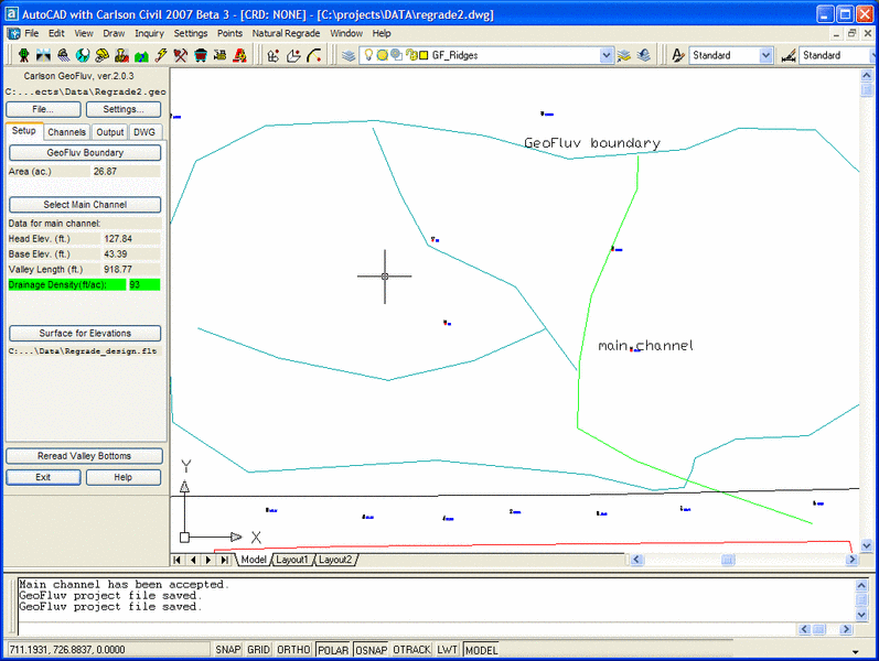
GeoFluv™ helps the user create a stable landform based on minimal
local input variables. These include site elevations (from a survey
grid), a GeoFluv™ project boundary, a local stream base level to
which the area within the GeoFluv™ boundary drains, a desired
drainage density, design maximum discharge velocity, precipitation
from the 2-yr, 1-hr and 50-yr, 6-hr storms, and runoff coefficient.
The user will also select a desired cut/fill balance tolerance.
Figure 3 shows an example of the minimal input data needed for the
software to design the landform using this fluvial geomorphic
approach.
|
|
| Figure 3. Example of Setup tab input dialog box |
The user can then edit this idealized landform for any number of
reasons. The site may have boundaries that must be avoided. The
user may want to bend a channel around an archaeological or
historic site, or local landmark. The user may want to alter slope
aspects to promote vegetation diversity, wildlife niches, or to
harvest moisture by retaining snow. Aesthetic considerations, such
as view sight line, may prompt the user to edit the draft landform.
Material movement planning may require the user to evaluate factors
including the cut/fill balance and haul distances associated with
various alterations of the draft landform. The user may wish to
create several interim landform designs leading to the final design
for submission for incremental reclamation bonding. The ease and
speed by which the software creates a draft design solution
facilitates these and other edits. The Natural Regrade module frees the user
to focus on site-specific design considerations and finding an
optimal solution to creating a stable site landform, rather than
being immersed in ponderous calculations for each subwatershed.
Following the discussion of input parameters below, the Settings
button default settings on the Setup tab will be explained. These
settings are one way that the draft landform can be edited.
Drainage Density and Channel
Pattern
The drainage density input is the valley length (without meanders)
divided by the subwatershed area (Dunne and Leopold, 1978). Its
units are length over area (L/L2).
Convenient U.S. units for landscape design work are feet/acre. This
value will vary depending on factors such as earth materials, slope
aspect, storm intensity, and vegetation type and coverage.
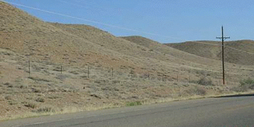
Drainage density is important because it represents the subwatershed size that will be stable for the local conditions. Drainage density and the ridges that form between channel meanders work together to break up the landform into many small subwatersheds, as can be seen in the natural subwatershed shown in Figure 4. The subwatersheds minimize both slope length and catchment area and thereby minimize erosion.

|
| Figure 4. Natural “A” channel meanders and ridges break slope length into a series of subwatersheds |
The drainage density is an expression of the amount of erosion
that has occurred in the watershed. In a stable watershed, it
represents the state at which sediment supply and water runoff are
balanced in a state of dynamic equilibrium. Designing the landform
using an appropriate drainage density for the project area
conditions is an important first step toward achieving a stable
landform design.
Watersheds may be disturbed in different ways and those affect
reclamation planning differently. For example, mining may break up
consolidated rock in the watershed and replace it with
unconsolidated material. The result of this change on watershed
reclamation design is often a marked change in channel pattern.
Channels exploit weak portions of consolidated rock and tend not to
form on more resistant portions, that is, the channel pattern has
structural control. In the disturbed, unconsolidated material, the
channels may form anywhere. Streams that previously had patterns
that followed cracks in the consolidated rock can now form a more
random pattern in the unconsolidated material. A different drainage
pattern with greater drainage density may be expected in the
unconsolidated, disturbed material for these reasons.
The effects of land leveling, whether for road building, urbanization, agriculture, or other purpose, may be nearer to the land surface and may not affect structural rock as much as an activity like mining might. The adverse effects of these land disturbances can still be unacceptable. Often these activities result in a decrease in drainage density and associated diversion of runoff from several watersheds into another watershed that is not adjusted to that flow. Runoff water may accumulate in undesirable parts of the leveled land and an undersized receiving watershed may respond to an increased flow with erosion and excess sediment production. Reclaiming these lands disturbed by leveling with an appropriate channel pattern and drainage density can mitigate the effects of the prior disturbance.
GeoFluv™’s default drainage pattern is a dendritic pattern, because this “branching tree” pattern is the type that typically forms in unconsolidated materials (Bloom, 1978; Dunne and Leopold, 1978), such as those existing at a disturbed site. Drainage patterns other than the dendritic pattern generally express structural controls related to rock (or soil) mineralogy. Streamflow will not tend to maintain variation from the dendritic pattern when reclaiming unconsolidated materials without reestablishment of a structural control, e.g., rock-lined stream banks. Installing structural controls will add cost, will establish a point of weakness subject to attack by flowing water, and can cause disruption in the flow regime up- and downstream of the structure that will require compensation in the channel designs there.
Determining appropriate
reclamation drainage density
GeoFluv™ suggests a default drainage density value, but the user
can, and must,
determine site-specific values to achieve landform stability
comparable to surrounding natural land. By using empirically
determined drainage density values in GeoFluv™’s input, the user
can have a very high degree of confidence that the resulting design
will behave similar to the areas from which the drainage density
measurements were taken.
The user can determine a desired range of site-specific drainage
density values. Local drainage density measurements taken from the
undisturbed land with earth materials similar to the project area,
and from nearby areas with earth materials that are similar to the
project’s disturbed earth materials, can define the range. The
drainage density measured on undisturbed earth materials provides a
lower end-of-range value, while the drainage density measured on
nearby areas similar to the project’s disturbed materials provides
an upper end to the range of desirable drainage density input
values.
The recommended procedure for determining drainage density
values is to visit the field site with a map and to mark the
location and length of each valley feature that, if it were to
erode into a finished reclamation landscape, would be large enough
to be considered undesirable. Many of these features that will be
identified in the field would not be apparent when examining a 7.5
minute quadrangle. It is important to recognize that when different
individuals determine drainage density values for the same stable
watershed, their results will vary. One individual may map a
slightly smaller feature and generate a greater drainage density
value than another observer, or vice versa. For this reason, it is
recommended that the same individual make all the determinations
for design consistency.
Entering Drainage Density
Values
The user draws a GeoFluv Boundary and sketches a draft channel
pattern inside the boundary. The appropriate pattern for
unconsolidated, disturbed material is typically a dendritic
pattern. The channels should be spaced so as to divide the
GeoFluvTM work area into roughly equal
portions. The user then identifies the GeoFluv Boundary in the
Setup tab by pressing the Select GeoFluv Boundary button and then
selecting the boundary on screen with the cursor. The software
calculates and displays the watershed area.
The user then clicks on the Select Main Channel button to identify which channel segment in the drainage pattern will collect discharge from all the tributary channels and convey it out of the watershed at the watershed’s base level. Regrade will display on the Output tab the length of the main channel selected and calculate the GeoFluv™work area drainage density that the user has sketched. If the reclamation drainage density is too low, the natural watershed response would be to erode material until the appropriate drainage density is achieved. If the software’s indicated value is too low as compared to the desired design value, the user can lengthen or add channel segments until the desired drainage density is attained. Conversely, if the indicated value is too high, the user can shorten or remove channel segments. If the design drainage density is too high, erosion is not likely, the landform may even be more resistant to erosion, but earthwork costs would increase beyond that which is necessary to create a landform as stable as surrounding natural lands.
Sinuosity
Sinuosity is the ratio of channel length to valley length. A stream
flowing in unconsolidated material will typically begin to meander
as it flows down slope. Because of this, the distance that the
stream flows is greater than the straight line distance from the
stream’s head to its mouth. Sinuosity is calculated using units of
length over length (L/L) and is a dimensionless value greater than
1.0 when any meandering is present. After the user has input the
channel pattern and accepted a pattern with the desired drainage
density, this software will then draw a draft channel pattern with
suggested sinuosity appropriate to the channel slope. Channels on
steeper slopes generally are less sinuous than those on lower
gradients in stable land forms. The user may edit the draft
channel’s sinuosity value using the Channels tab's 'Current Channel
Settings...' button.
Channel Longitudinal
Profile
Following the development of the channel pattern with sinuosity,
GeoFluv™ calculates channel longitudinal profiles for each channel
in the draft drainage pattern. The longitudinal profile of a
natural channel is typically concave (Dunne & Leopold, 1978),
steeper gradient in the headwater reaches and lower gradient near
the channel mouth. That is because the headwaters of the watershed
have less area, and therefore generate less runoff and erosive
energy than the reaches near the channel mouth. Steeper channel
gradients can be stable in the upstream reaches and lower channel
gradients are appropriate in the downstream reaches for this
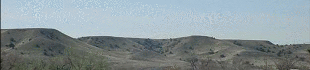
reason. Stable slope profiles also tend toward this profile as can
be seen in Figure 5.
|
| Figure 5. Concave longitudinal profiles in stable natural slopes |
Determining appropriate channel
reclamation longitudinal profile
GeoFluv™ designs the
longitudinal profiles for the draft landform to grade concave
profiles to each local base level. For example, the main valley
bottom channel in the draft GeoFluv Boundary work area grades to
the user-input local base level (the lowest elevation in the
design’s main channel, typically where all runoff leaves the
GeoFluv Boundary). GeoFluv™ grades each valley wall channel, at its
confluence with the main valley bottom channel, to the main valley
bottom channel slope at their confluence. The headwater slope for
the design profile can be automatically determined by the elevation
of the design's GeoFluv™ Boundary and a default distance from that
boundary over which the ridgeline can have a convex profile and be
stable, or can be user specified using the Channels tab's 'Current
Channel Settings...' button.
Entering Longitudinal Profile
Values
When the user identifies the GeoFluv Boundary in the Setup tab by
pressing the Select GeoFluv Boundary button and then selecting the
boundary on screen with the cursor,
GeoFluvTM uses the boundary elevation to
calculate a channel head elevation for each channel in the
watershed from the Surface for Elevations file. The user specifies
the three dimensional surface file that GeoFluv™ will use as a
beginning surface from which to create its fluvial geomorphic
landform design using the Surface for Elevations button. Examples
of Surface for Elevations include existing post-disturbance
topography designs or pre-disturbance topography. The user can type
in the file path and name or use the browse button to help locate
the desired file. The user may also enter Head Elevation and Base
Elevation values using the Channels tab's 'Current Channel
Settings...' button manually to gain accuracy; this is
highly recommended
for the base level elevation. The base level elevation has
great effect on watershed response and an interpolated elevation
may vary by several feet from the actual elevation. If the sketched
channel begins beyond the default maximum distance from the GeoFluv
Boundary, a pop-up warning will advise the user of this condition.
The user may then either extend the channel to be within the
default value or reset the default distance using the Settings
button if local conditions permit a greater distance without
erosion. The result of GeoFluv™'s longitudinal gradient solution is
a network of sinuous channels that have concave profiles and
smoothly transition from steeper headwater gradients to the
gradient at the design watershed’s local base level elevation.
Figure 6 shows an example of a natural stable network of slopes and
channels with concave longitudinal profiles graded together from
steeper ground to a lower gradient valley bottom.
|
| Figure 6. Stable natural channels
and slopes grade from steep to flatter gradient by a network of concave longitudinal profiles |
The Profile button allows the user to review the design longitudinal profile for the current channel. It displays the beginning and ending channel elevations, the profile, and by moving the cursor, stationing is depicted along the profile along with the elevation and slope at that station. The viewer allows for vertical exaggeration to aid work on lower relief channels. The viewer also has toggle settings for pan/zoom and tick mark options. The Natural Regrade drop-down menu has powerful editing commands for channel and slope longitudinal profiles for special situations.
Channel
Cross-section
GeoFluv™ calculates the channel cross-sectional profiles for
channel reaches. The bankfull width (Dunne and Leopold, 1978)
(Rosgen, 1996) for the mean annual flow is used to create a
hydrologically balanced cross section. GeoFluv™ uses the input
runoff coefficient, maximum water velocity, 2-yr, 1-hr storm
precipitation, and width to depth ratio values to create this cross
section. As the watershed area increases downstream, more water is
present in the channels and the channel cross sectional area must
increase to convey the discharge within the user-specified design
velocity range. Other channel pattern dimensions, i.e., meander
length, meander belt width, radius of curvature, related to the
bankfull discharge (Williams, 1986) increase concurrently.
GeoFluv™’s cross sectional area increase occurs simultaneously with
the other channel dimensions. Channel flood-prone area has been
related to a 50-year recurrence interval event (Rosgen, 1996) and
GeoFluv™ uses this value to design the flood-prone area of the
channel. The resulting dimensions define the channel banks for the
draft landform. The designer can get cross section information by
station for any channel in the GeoFluv design using the Channels
tab's Report button. The range of design dimensions can also be
seen using the Output tab's Summary Report button. A reviewer can
get cross section information by station for any channel in the
GeoFluv™ design from a completed drawing using the Natural Regrade dropdown menu's
GeoFluv™ Channel Cross-section Report command.
Ridges, Slopes, and VolumesGeoFluv™ designs ridgelines between the channels at elevations that create side slopes less than a default 5:1 gradient for the draft landform. The Preview button in the Output tab will display the location of the main ridges, and the subridges and subridge valleys that form around the channel bends. The user may alter the elevation and placement of the ridgelines to adjust slope gradient and material balance. The Draw Design Surface button in the Output tab is used to contour the ridgelines and channels to reveal the draft landform. The Save Design Surface button in the Output tab saves the landform drawing as a file.
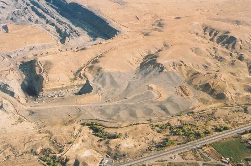
Figure 7 shows a reclamation project midway through construction
that used this fluvial geomorphic approach. The mine pit highwall
that ends at the graded gray spoil used to continue trending to the
right of the figure and then turned ninety degrees toward the lower
right of the figure. The steep slope reclamation with four
subwatersheds immediately to the right of the end of the pit is the
same slope shown in Figure 2 above. This project was designed over
a period of months without the benefit of the computerized
software; using Natural
Regrade with GeoFluv™, the design time would be measured in
hours.
|
| Figure 7. Fluvial geomorphic reclamation is underway at the 115-acre Cottonwood Reclamation Project, Farmington, New Mexico. Gray colored material is mine spoil being graded using fluvial geomorphic approach. The U.S. Department of the Interior awarded San Juan Coal Company "National" and "Best of the Best" reclamation awards for 2004 for this project. |
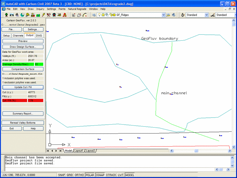
GeoFluv™ calculates and displays the material balance needed to
create the draft landform. The GeoFluv™ design’s material balance
is calculated by comparing the GeoFluv™ design surface to the
surface file identified as the Comparison Surface. The user could
compare the Design Surface to the pre-disturbance surface, another
post-disturbance reclamation surface design, the existing disturbed
surface, or other surface file. Figure 8 is an example output
dialog box that compares the cut to the fill needed to create the
landform.
|
| Figure 8. Output dialog box gives immediate cut/fill balance to guide landform design editing |
Note that the Output tab also displays the overall drainage density with the GeoFluv work area, which can be compared with the current channel drainage density. The user can compare the drainage density that is displayed in the Channels tab for each channel’s subwatershed to the overall watershed drainage density to verify that the drainage density is uniform throughout the watershed. Subwatersheds that have too great or small drainage density values can be corrected by editing ridges or channels to vary areas or channel lengths.
The Output tab and the Summary Report show whether or not the balance is within the user-specified tolerance. The Summary Report button in the Output tab generates a report for the channel showing the design parameter values of the channel and valley slopes. The report also displays the parameter values for natural channel types in the Rosgen stream classification scheme for ready comparison.
The draft landform is an idealized solution to creating a stable
landform according to fluvial geomorphic principles based on the
user-specified input values. The user may modify the draft
landform, for example to reduce the fill volume by lowering a
ridgeline using the Edit Longitudinal Profile or Auto Longitudinal
Profile commands, and the software can almost instantaneously
recalculate the cut/fill balance to meet the user’s design.
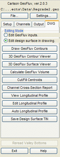
The DWG tab lists the tools for analyzing the Design Surface as it is represented in the drawing in the channels and ridges layers (GF_Channels and GF_Ridges by default). These are the same commands that are in the Natural Regrade menu plus the addition of Save Design Surface TIN. The Save Design Surface TIN command will save a TIN file of the current Design Surface (as it is represented in the drawing) and is simply the built channels and ridges within the GeoFluv boundary. The Editing Mode toggle helps to clarify the difference between editing a GeoFluv input and editing a Design Surface in the drawing.
The Fluvial Geomorphic Characteristics of the Draft LandformThe fluvial geomorphic characteristics of the draft landform are
those that are compatible with unconsolidated materials placed at
various slopes, subject to particular storms, and considering
special limitations of typical reclamation sites. Those special
limitations include a relatively thin topsoil veneer over mixed
earth materials (spoil), equipment limitations (e.g., equipment
grading capability versus design grading requirements, ability to
traverse steep slopes), and desire to minimize cost and
maintenance.
The GeoFluv™ fluvial geomorphic approach to building stable
reclamation landforms is centered on creating a network of
ephemeral drainage channels and associated slopes that are in a
state of quasi-equilibrium, i.e., that are “stable.” Natural
ephemeral channels are the landscape’s response to runoff events.
By definition, they flow now only in response to direct
precipitation. However, they may have formed in response to greater
precipitation during wetter climatic conditions, including glacial
periods, when they may have flowed as intermittent or even
perennial streams. Considering that, their water and sediment
transport characteristics would be expected to be consistent with
streams that flow perennially in the present climate.
For this discussion, we will use the Rosgen classification
scheme for natural channels. The Rosgen scheme classifies perennial
streams according to major types based on slope, width to depth
ratio, entrenchment ratio, and sinuosity (see glossary for
definitions), and stream bed material particle size (1 through 6,
where 1=bedrock and 6=silt/clay). The Rosgen classification scheme
describes natural channels as major types A through G using
characteristics of multiple and single thread channels that form in
different geologic settings.
Slope is generally considered the dominant characteristic, and
only the type A and A+ channels are associated with slopes greater
than -0.04. For this reason, the A and A+ channel types have a
place in many reclamation landscape designs.
Some of these channel types, such as the multiple-thread D and
single-thread F and G, are associated with high bank erosion rates
and sediment transport and deposition. They tend to exist as
transitional channel forms as the channel moves towards a more
stable type and for this reason are not favored for use in a stable
reclamation landscape design.
The B type is a step-pool stream with low sinuosity, with the
steps typically formed by resistant rock strata and narrow rock
canyon walls limiting sinuosity. Because both of these structural
elements are typically gone in a reclamation landscape, the B type
channel is not favored in stable reclamation landscape design
either.
The remaining major types, the C and E, differ mainly in their
width to depth ratios and sinuosities, and the stable E type’s
association with dense bank vegetation. The low width to depth
ratio of the E-type develops where the combination of cohesive bank
material and a dense network of roots from bank vegetation are
present. The E type channel is stable, but is very sensitive to
disturbance of its bank material and vegetation. The C type has a
tendency toward lateral migration through the process of erosion at
the cut bank and deposition on the point bars, a tendency that is
also exacerbated by bank material and vegetation
disturbance.
From this discussion, it can be concluded that the characteristics of the A, C, and E major types have advantages for stable reclamation channel design. Further, the major channel types do not exist as distinct and separate entities, but in an evolutionary continuum from one type to another. For example, a B5c stream would have the major characteristics of a B channel with dominantly sand-size material, but its flatter slope, greater sinuosity, and width-to-depth and entrenchment ratios, would be tending toward those associated with type C streams. The flatter slope of this stream type combined with its greater sinuosity can allow it to transport and balance its water and sediment loads by channel geometry and not require the structural drops associated with the major B-type’s step/pool sequences. Its width-to-depth and entrenchment ratios are such that all but extreme events may remain within a flood prone area within its channel banks. When its hydraulic design is correct and its banks are sufficiently protected by vegetation, natural appropriate channel roughness, and bank protection such as rock deflectors or J-hook vanes, this channel type can convey water and sediment discharge with minimal changes to the channel pattern. In other words, the channel can maintain its course and not erode into its banks and through the relatively thin veneer of topsoil because sediment transport and deposition occurs within the channel. When floods greater than the flood-prone capacity (based on entire 50-year, 6-hr recurrence interval precipitation introduced to the channel instantaneously in the GeoFluv™ approach) occur, the additional discharge energy can be rapidly dissipated on an adjacent floodplain.
The default channel-type settings create type A and A+ channels at slopes greater than -0.04 and type Bc channels for slopes less than -0.04 using lower-range channel geometry values for these types. The user can also optionally choose to randomly vary the channel geometry values within the acceptable range using the Channels tab's 'Current Channel Settings..." button. GeoFluv™displays the channel geometry values for all channels and reaches of longer channels in the watershed in the Summary Report. The user can then edit the channel settings within the ranges of value appropriate to the default channel types or vary the settings to use different channel types.
| Converted from CHM to HTML with chm2web Standard 2.85 (unicode) |