2D Polyline

This command creates a 2D polyline. A Polyline is a complex CAD entity comprised of one or more line or arc segments. While a 2D polyline elevation isn't necessarily zero, a 2D polyline is flat with all vertices at the same elevation.

This command is available from the Draw pulldown menu, from the Draw toolbar or at the Command: line (2DP) and provides many more options than the 
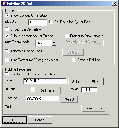
standard CAD version of the command. Unless disabled, the Polyline 2D Options dialog box will appear after starting Carlson's 2D Polyline command.

Show Options on Startup: When this option is enabled, the Polyline 2D Options dialog box will display automatically upon starting the 2D Polyline command. If disabled, you can still get to this dialog by typing O for Options at the command prompt.

Elevation: Set the elevation of the polyline to be drawn. The Set Elevation By 1st Point option will use the elevation from the first specified point for the whole polyline.

Offset from Centerline: If this option is enabled, an additional option, Offset, is available from the Command: line. Issuing the "Offset" option allows you to draw a new polyline using Station and Offset entry from an existing polyline or existing Centerline (.CL) file.

Skip Inline Vertices for Extend: This setting applies to the "Extend" option with the Total Distance SubMenu option. If enabled, an existing vertex will dissolve when lengthening a 2D Polyline segment.

Prompt To Draw Another: This option stays in the command after completing the polyline and prompts whether you want to draw another polyline.

Auto-Zoom Mode: This setting provides 3 options for Auto-Zoom: Never, Proximity or Always. The "Never" setting requires you to manually Zoom or Pan to keep the current polyline vertex centered in the drawing screen. The "Proximity" setting will activate the "Proximity Level" setting and will automatically re-center the view only if the current polyline vertex is within a certain distance of the limits of the drawing area. The "Always" option will automatically re-center the view after each new polyline vertex is added.

Annotate Closed Pads: Enabling this option will activate the "Settings" button. The "Settings" button displays the Label Pad Elevations dialog box where you can specify label settings for the pad and other vertical offset elevations. For instance, you can label both the Finished Floor Elevation and the SubGrade elevation of a building pad at the same time using this command. See additional information on the Label Pad Elevation command.

In the "Polyline Properties" section of the dialog box you have several alternatives for specifying the layer, color and linetype of the newly created polyline.

Auto-Correct For 90 Degree Corners: This option will adjust two line segments to make an exact 90 degree corner when the original lines are nearly 90 degrees.

Smooth Polyline: This option applies for drawing smooth polylines such as a path for a stream. The Bezier smoothing method is used which passes through all the points and smooths only between the points.

Use Current Drawing Properties: Select this option if you want the layer, color and linetype of the newly created polyline to match those currently set in the drawing.

Layer: Use this setting to manually assign the layer for the newly created polyline. You can type in the new layer name, use the "Select" button to choose an existing layer from the drawing's layer list or use the "Pick" button to select an entity in the drawing and match its layer.

Set Color: Use this button to manually specify a color for the newly created polyline.

Width: Specify the width of the newly created polyline.

Linetype: Use the "Select" button to manually specify a linetype for the newly created polyline.

Select Code: This option allows you to set the layer, color and linetype of a new polyline by using the properties assigned to a Field to Finish field code. The field code is selected from an existing Field Code table (.FLD) file that has been previously specified in the Point Defaults dialog box.

Prompts

Command:2dp
[Continue/Extend/Follow/Offset/OPtions/<Pick point or point numbers>]: screen pick a point
[Arc/Close/Distance/Follow/Offset/Undo/<Pick point or point numbers>]: screen pick a point
Segment length: 202.55, Total length: 202.55
[Arc/Close/Distance/Extend/Follow/Line/Offset/Undo/<Pick point or point numbers>]: screen pick a point
Segment length: 179.73, Total length: 382.28
[Arc/Close/Distance/Extend/Follow/Line/Offset/Undo/<Pick point or point numbers>]: screen pick a point
Segment length: 127.45, Total length: 509.73
[Arc/Close/Distance/Extend/Follow/Line/Offset/Undo/<Pick point or point numbers>]: press Enter
Command:

Options and SubMenu Options

Once all settings have been specified and the "OK" button is picked, the options shown below are available from the Command: line. To issue any of these options, simply type in the capitalized portion of the Option at the Command: line and press Enter. The default option is always shown between angle brackets < Default >.

Continue: This option allows you to select an existing polyline to which you'd like to add more line or arc segments. When prompted to "Select a polyline to continue or extend:", you may pick anywhere on the existing polyline and the new segment will begin at the ending vertex nearest your cursor. New line or arc segments can be added by screen-picking or using the options at the Command: line. Once finished adding segments, they are automatically joined to the original polyline.

Extend: This option gives you many ways to lengthen or shorten an existing polyline using the abbreviated SubMenu options shown below. Some of these options create additional segments at the end of the existing polyline and some allow you to change the length of the ending segment of the polyline. When prompted to "Select a polyline to continue or extend:", you may pick anywhere on the existing polyline and the "Extend" will occur at the ending vertex nearest your cursor. Once finished Extending, the new segments are automatically joined to the original polyline.

[I / R / L / S / T / A / B / E / U / X / Help / <Enter or Pick Distance>]

I - Input mode - This option toggles the distance input between feet & inches (will prompt first for feet, then prompt again for inches) and decimal feet.
R - Right rotate - From the ending vertex, turns the pointer 90-degrees to the right and then prompts for a distance.
L - Left rotate - From the ending vertex, turns the pointer 90-degrees to the left and then prompts for a distance.
S - Switch direction - From the ending vertex, turns the pointer 180-degrees and then prompts for a distance.
T - Total distance - Prompts you to "Enter total distance (100.00)" and displays the current length of the segment in parentheses. If a number smaller than the current distance is entered, this option will shorten the existing segment. If a number larger than the current distance is entered, this option will lengthen the existing segment. This option is also affected by the Skip Inline Vertices for Extend setting in the Polyline 2D Options dialog box. If "Skip Inline Vertices for Extend" is enabled, then the existing vertex will be dissolved when lengthening a segment. If the setting is not enabled, then the existing vertex will be left intact and an additional segment will be created inline.
A - Angle change - From the ending vertex, prompts you to "Enter Angle (ddd.mmss):" to turn the pointer by a specified angle and then prompts for a distance.
B - Bearing/Azimuth/Turned/Deflection - From the ending vertex, this option allows you to set the pointer direction by specifying an Angle. The Angle format is Qdd.mmss and there are a variety of ways to use the "Q" value to specify the Angle. See here for more.
E - Extend to edge - Extends current segment to another line or entity
U - Undo - Undo last action
X - Quit extend mode - Returns to normal 2D Polyline Draw mode
Help - Displays the descriptions of the Extend options
Enter or Pick Distance - Distance to extend the current segment

Follow: This option allows you to trace all or a portion of an existing polyline. After issuing the "Follow" option, you are prompted to "Select the polyline to Follow:" and then to "Specify the first follow point:". After snapping to a starting point on the polyline, you are asked whether you want to "Interpolate follow vertices elevations?". With this being a 2D Polyline, the answer to this is most likely "NO". You will then be prompted to specify the "Last follow point or follow distance:" where you can snap to another point on the polyline or type in a distance to trace the existing polyline.

Offset: With the "Offset" option, you will first be prompted to select an existing polyline or select an existing Centerline (.CL) file. Next, you will be asked to "Specify starting station:" where you will enter the station number of the first polyline vertex. Then, you will be prompted to "Enter Station" and "Enter Offset" for each vertex of the new polyline. Note: To have this option available, you must place a check next to Offset From Centerline in the Polyline 2D Options dialog box.

Pick Point or Point Numbers: This is the default prompt for the command. From here you can set a new polyline vertex by screen picking, entering coordinates in X,Y format or entering a point number from the associated Coordinate (.CRD) file.

Arc/Line: New polyline segments can be either an Arc or a Line segment. If the last polyline segment drawn was a LINE, then the "Arc" option will be shown as an available option; however, if the last polyline segment drawn was an ARC, then the "Line" option will be available.

When in the "Arc" mode, there are many additional SubMenu options available to you for creating an arc segment within the new polyline. The options are generated directly from the standard CAD version of the PLINE command and include Radius Point, Radius Length, Arc Length, Chord and Second Point (Point on Curve).

Close: This option will create a new Line or Arc segment back to the starting vertex of the polyline and results in a closed polyline.

Distance: This option allows you to first enter a distance for the new Line segment and then to specify the direction using one of three methods: Cursor, Line or Angle.
Cursor - This method will draw the polyline segment in the direction of your cursor position.
Line - This method prompts you to select a line or polyline segment to which it will draw a parallel segment.
Angle - This method prompts you for an Angle to determine the direction of your new polyline segment. The Angle format is Qdd.mmss and there are a variety of ways to use the "Q" value to specify the Angle. See here for more.

Undo: Undo the last drawn polyline segment.

Angle Entry Methods
The Angle format is Qdd.mmss where: Q=quadrant/angle, d=degrees, m=minutes and s=seconds.
The Quadrant/Angle can be specified as:
1=NE (NorthEast)
2=SE (SouthEast)
3=SW (SouthWest)
4=NW (NorthWest)
5=AZ (AZimuth)
6=AL (turned Angle-Left)
7=AR (turned Angle-Right)
8=DL (Deflection angle-Left)
9=DR (Deflection angle-Right)

Pulldown Menu Location: Draw
Keyboard Command: 2DP
Prerequisite: None

Converted from CHM to HTML with chm2web Standard 2.85 (unicode)