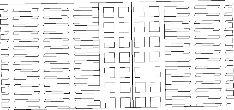
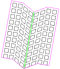
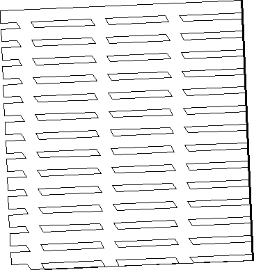
Based on the preceding dialog box responses, the following mine layout is created:
Advanced Projections is a flexible routine that is an extension
of Basic Projections. Besides creating projections this routine can
also draw pillars and perimeter by using the Draw Pillars option.
Other options include angling the crosscuts, offsetting entries,
variable length entries, and different labeling schemes. All
projection lines are on distinct layers with defaults of
PROJECTIONS, PROJSTOPPINGS, PROJVENTARROWS. The pillars are drawn
by default in the PILLARS layer and the perimeter is drawn by
default in the PERIM layer.
Pick Start Point For Belt: pick a point
Pick End Point For Belt, or <A> For Azi/Dist:
A
Enter Azimuth ddd.mmss <>: 90
Enter Distance: 600
How Many Entries Left Of The Belt <0>: 3
How Many Entries Right Of The Belt <0>: 3
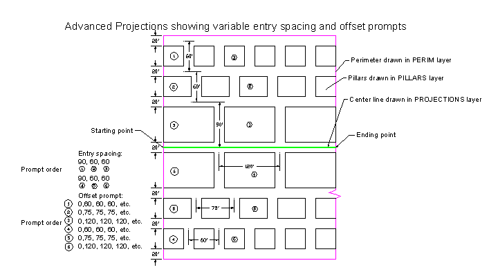
Based on the preceding dialog box responses, the following mine
layout is created:
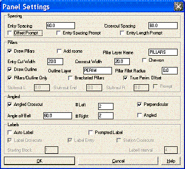
 To create various entry spacings
and lengths choose the Offset Prompt, Entry Spacing Prompt, and/or
Entry Length Prompt check boxes.
To create various entry spacings
and lengths choose the Offset Prompt, Entry Spacing Prompt, and/or
Entry Length Prompt check boxes.
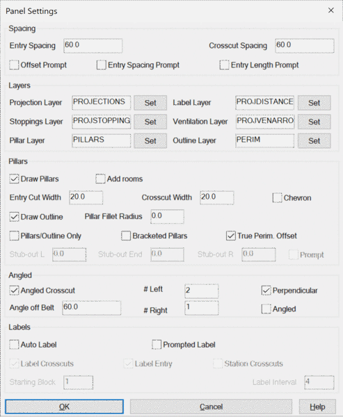
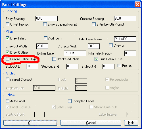
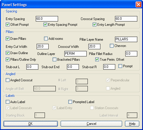 Panel Settings Dialog
Spacing for Left Entry No. 1 <60.0>: 90
Spacing for Left Entry No. 2 <60.0>: press Enter
Spacing for Left Entry No. 3 <60.0>: press Enter
Spacing for Right Entry No. 1 <60.0>: 90
Spacing for Right Entry No. 2 <60.0>: press Enter
Spacing for Right Entry No. 3 <60.0>: press Enter
Enter Offset For This Heading <0>: press Enter
First Length along Entry: 60
Enter Length along Entry <540.0>: 60
Enter Length along Entry <480.0>: 60
Enter Length along Entry <420.0>: 60
Enter Length along Entry <360.0>:60
Enter Length along Entry <300.0>: 60
Enter Length along Entry <240.0>: 60
Enter Length along Entry <180.0>: 60
Enter Length along Entry <120.0>: 60
Enter Length along Entry <60.0>: 60
Enter Offset For This Heading <0>: 0
First Length along Entry: 75
Enter Length along Entry <525.0>: 75
Enter Length along Entry <450.0>: 75
Enter Length along Entry <375.0>: 75
Enter Length along Entry <300.0>: 75
Enter Length along Entry <225.0>: 75
Enter Length along Entry <150.0>: 75
Enter Length along Entry <75.0>: 75
Enter Offset For This Heading <0>: press Enter
First Length along Entry: 120
Enter Length along Entry <480.0>: 120
Enter Length along Entry <360.0>: 120
Enter Length along Entry <240.0>: 120
Enter Length along Entry <120.0>: 120
Enter Offset For This Heading <0>:
First length along Entry: 60
Enter Length along Entry <540.0>:
60
Enter Length along Entry <480.0>: 60
Enter Length along Entry <420.0>: 60
Enter Length along Entry <360.0>: 60
Enter Length along Entry <300.0>: 60
Enter Length along Entry <240.0>: 60
Enter Length along Entry <180.0>: 60
Enter Length along Entry <120.0>: 60
Enter Length along Entry <60.0>: 60
Enter Offset For This Heading <0>:
First length along Entry: 75
Enter Length along Entry <525.0>: 75
Enter Length along Entry <450.0>: 75
Enter Length along Entry <375.0>: 75
Enter Length along Entry <300.0>: 75
Enter Length along Entry <225.0>: 75
Enter Length along Entry <150.0>: 75
Enter Length along Entry <75.0>: 75
Enter Offset For This Heading <0>:
First length along Entry: 120
Enter Length along Entry <480.0>: 120
Enter Length along Entry <360.0>: 120
Enter Length along Entry <240.0>: 120
Enter Length along Entry
<120.0>: 120
Note: The length of the panel was shortened for display
purposes. The PILLARS and PERIM layers are reserved layer names
used in other routines in Carlson. The layer names can be changed
here if you have other reasons to do so.
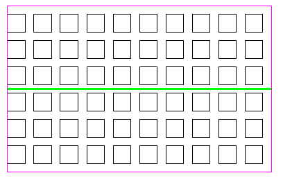
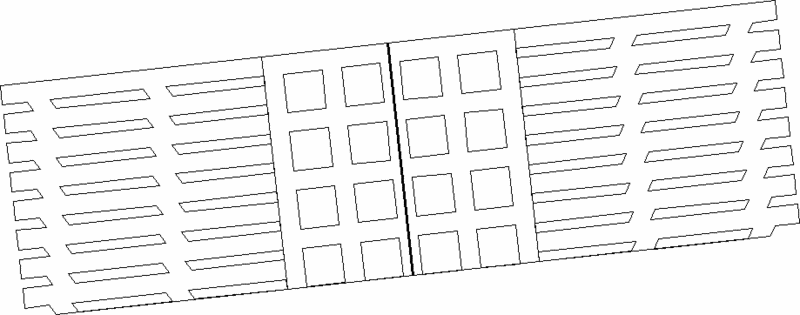
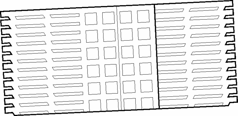
If you want to display the centerlines with the projections and
be prompted for ventilation symbols (stoppings and ventilation
arrows), then at the Panel Settings dialog box uncheck the Draw
Outline and Pillars only checkbox.
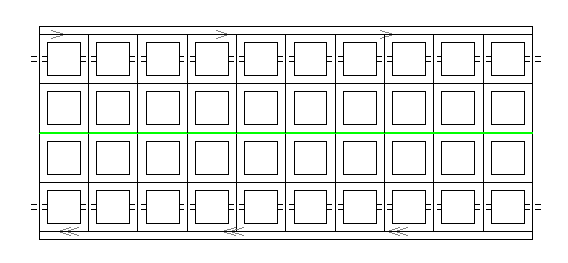
 The following panel layout is
drawn without the ventilation stoppings or arrows.
The following panel layout is
drawn without the ventilation stoppings or arrows.
 Then you will see the Stoppings
& Ventilation dialog box and upon filling it out you will be
prompted as follows:
Then you will see the Stoppings
& Ventilation dialog box and upon filling it out you will be
prompted as follows:
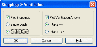 Stoppings & Ventilation
Dialog
Stoppings & Ventilation
Dialog
Pick pt. on xcut for beginning of stopping line: screen
pick
Draw another stopping line <y>/n: Y
Pick pt. on xcut for beginning of stopping line: screen
pick
Draw another stopping line <y>/n: N
Pick pt. on entry to begin drawing ventilation arrows [nea on]:
screen pick
Distance between ventilation arrows: 200
<I>ntake or [R]eturn: I
Draw ventilation arrows on another entry <y>/n:
Y
Pick pt. on entry to begin drawing ventilation arrows [nea
on]: screen
pick
Distance between ventilation arrows: 200
<I>ntake or [R]eturn: R
Draw ventilation arrows on another entry <y>/n:
N
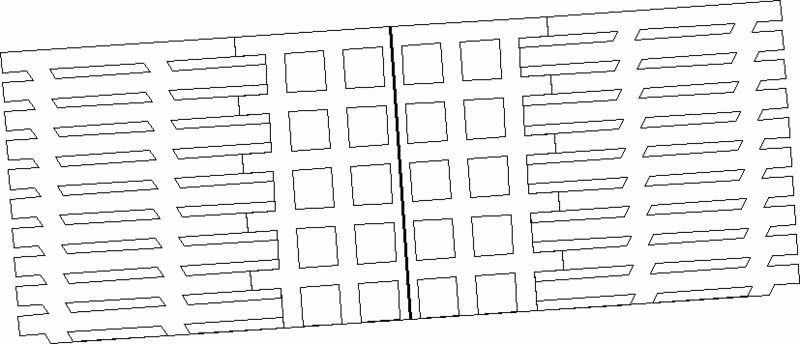
Upon filling in
the prompts, the map will be drawn as shown above.
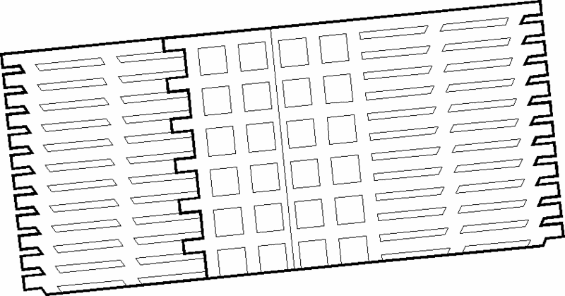
Angled Projections
It is possible to plot projections as centerlines, as pillars with
a perimeter, or both. Within the Pillars section of the dialog, if
the three dialog items on the left (Draw Pillars, Draw Outline,
Pillars/Outline only) are selected, then only pillars and
perimeters are drawn. This type of projection is particularly
useful to represent the actual mine for purposes of scheduling
equipment, using the Underground Mining Module. Here is an example
of angled projections, with a "winged" look created by angling only
the first 2 of 4 left and right entries:
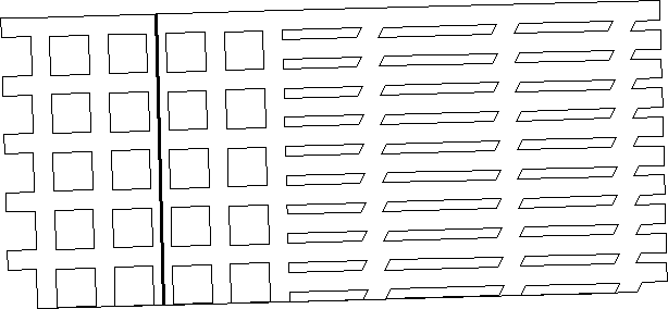
If all 4 entries left and right are angled (rather than the 2
above), then the entire projection would be in angled form.
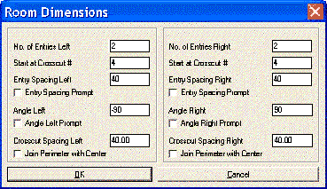
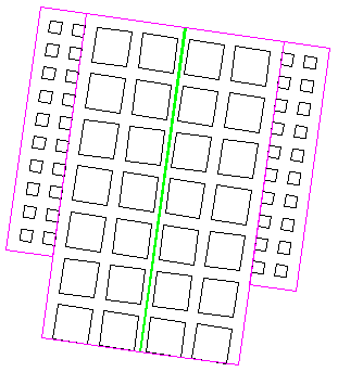
Add Rooms
Typical, Default Room Plotting requires that you click on the
left-side Draw Pillars, Draw Outline and Pillars/Outline only, as
well as click `Add Rooms'. A typical 2 left, 2 right standard
projection with 120' longrooms (current default) has the following
dialog appearance and plot.
The default angles lean the left rooms to the left and the right rooms to the right at 60 degrees. The crosscut spacing on the longrooms default to ½ the crosscut spacing on the main projections (60 in our case). I have noticed some irregular rooms if you use different crosscut spacing left and right—in that case, it might be better to plot the right side or left side separately. If the Join Perimeter with Center option is not selected, the projections will be in 3 parts: left, center and right. The outer left and right "extents" of the perimeter default to 30' plus the distance to the center of the left- and right-most entries. In our case, that distance to the far entry is 2*120=240, meaning that the outer punchout is defaulting to 270' left and right. I can change that addition of 30' to any other desired number.
Rooms with Stubouts: You can add stub-outs within the
main dialog, and the rooms will attach appropriately. In this
example, Stub-out L and Stub-out R were set to 30.
Joining with Center Section: The next variation is to join a left or right section to the center (we don't allow joining all 3 at present). This can be done with or without stub-outs. To activate this option, turn on the Join Perimeter with Center option in the Room Dimensions dialog. Shown below is a left section joined to the center with no stubs involved. Below that is a right section joined with the center with stub-outs. The perimeters have been made bold for emphasis.
|
| Rooms with stubouts connected to a
standard panel |
Changing Angles in the Rooms: Rooms can have a variety of angles for cutting through. To allow variation in angles, turn on the Angle Left Prompt in the Room Dimensions dialog. In this example, we did _60 (the default), then 60 and 60 in 3 entry left room. We did not vary the right condition. The prompting for the angle will remember the last entry, so the second "60" becomes just an "Enter" default on the left side.
|
| Room with stubouts connected to a panel with stubouts |
|
| Left room connected to advancing panel |
|
| Right room connected to advancing panel |
|
|
| Angled rooms left (3+ X-cuts deep)
and angled room right (2+ X-cuts deep) Notice neither set of rooms were joined to the panel on the advance |
|
| Rooms with entry spacing variations |
Entry Spacing Prompt: We can also choose to vary the spacing. In the example below, we did 0 left entries and 3 right entries, and we varied the entry spacing prompt on the right (and included stub-outs and Join Perimeter with Center). We entered 100, 140 and 120 for the three entry spacings and obtained the plot shown below:
Plotting Rooms with No Central Projection: This is useful
for attaching left and right rooms to an existing mine plot. You
pick your "centerline" as normal to get starting, but you answer 0
to both the number of left and right entries. Normally, this would
simply exit the routine, but a new prompt asks "Do Longroom (y/n)".
Enter "y" and you can place rooms to the left or right. (The
program will only do one side or the other in a "no central panel"
projection scheme. Repeat the process to add a right side to the
left side rooms.) Here is the "look" of a left-side, 3 room
section with no central projection:
Perpendicular Rooms and Offset
Rooms
If the Room Dimension dialog is completed as shown below, rooms can
be drawn at 90 degrees to the main entry, and can be offset as many
crosscuts as desired. The offset up is measured by counting the
number of room-size crosscuts. So if you have 40x40 rooms coming
off 80x80 mains, and want to offset two main-size crosscuts (160
feet to the first rooms), then enter 4 (4*40 is 160) for the number
of crosscuts to offset. Here is the result:
Pulldown Menu Location: Works
Keyboard Command: panel2
Prerequisite: None