This command creates a solid model from a collection of x,y,z points by creating cross sections from the points and then stitching the sections together. The points need to cover all sides of the surface (top, bottom, left, right, front, back).
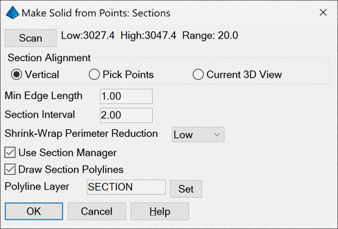
Scan: Reads the input points to find the min and max
elevations which are reported at the top of the dialog.
Section Alignment: Sets how to section the points. It is
important to align the sections with the data to get good sections.
For example, with a tunnel the alignment should go along the length
of the tunnel so that the sections are like slicing a carrot into
discs. The Vertical method slices by elevation range. The Pick
Points method prompts for two points and uses the 3D line between
these points for the alignment. The Current 3D View method uses the
CAD view. This way you can use the CAD 3D view commands to line up
a good view for the points.
Min Edge Length: Sets
the minimum length of a triangle edge in the solid. When there are
several points closer than this distance to each other, some of
these points will be left out of the solid model.
Section Interval: Sets the distance between sections along
the alignment. This distance needs to be big enough to ensure that
plenty of points are used for each section, and the distance needs
to be small enough to create enough sections to model the
solid.
Shrink-Wrap Perimeter Reduction: The program triangulates
the points for each section and uses the boundary of this
triangulation for the section. This option controls how much to
tighten this boundary polyline by removing long edges.
Use Section Manager: This option shows the generated
sections in an editor for making changes before building the
model.
Draw Section Polylines: This option draws 3D polylines for
the sections on the specified layer.
Select points to process.
Select objects: pick points
Points to Solid options dialog
Solid File To
Write Select MDL file
Pulldown Menu Location: Solid
Keyboard Command: pt2mdl
Prerequisite: points