This command edits a solid model (.MDL) by using cross sections.
This command is a way to review the solid model in sections and
make edits to the sections to correct the model such as for
removing nobs.
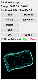
After selecting the solid model to process and choosing the
options in the dialog, the Section Manager dialog docks on the side
of the drawing. The Section Manager dialog shows all the cross
sections in a graphic window. You can choose the current section by
using the Top, Bottom, Up, Down buttons. The current section is
highlighted in white. Besides showing the section in the Section
Manager graphics windows, the section is also drawn in the drawing
window as a polyline. Use the Edit button to edit the current
section polyline in the drawing. The edit starts by picking a point
on the polyline to begin recreating. Then pick new points for the
section polyline. To complete the edit, press Enter at the prompt
for new points and then pick a reconnection point on the existing
polyline. The Show Adjacent option highlights the section above and
below the current section in green and red which helps visualize
how the current section transitions to its neighbors. The Delete
function removes the current section from the model. When you pick
OK on the Section Manager, the program rebuilds the solid model
from the sections and prompts for a new MDL file to save the
modified model.
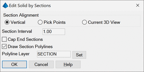
Section Alignment: Sets how to section the model. It is
important to align the sections with the model to get good
sections. For example, with a tunnel the alignment should go along
the length of the tunnel so that the sections are like slicing a
carrot into discs. The Vertical method slices by elevation range.
The Pick Points method prompts for two points and uses the 3D line
between these points for the alignment. The Current 3D View method
uses the CAD view. This way you can use the CAD 3D view commands to
line up a good view for the points.
Section Interval: Sets the distance between sections along
the alignment. This distance needs to be big enough to ensure that
plenty of points are used for each section, and the distance needs
to be small enough to create enough sections to model the
solid.
Cap End Sections: This option ends the model at the end
cross sections like the model getting sliced at the end sections.
Otherwise, the program uses all the model data points at the ends
and make a 3D triangulation for the model ends.
Draw Section Polylines: This option draws 3D polylines for
the sections on the specified layer.
Pulldown Menu Location: Solid
Keyboard Command: edit_solid
Prerequisite: solid model