Takeoff Trench Network Quantities
This lesson takes a drawing file through the
steps of trench network quantities in the Trench module.
Step 1 (Start Trench):
Click the icon for Carlson Trench on your
desktop or from the toolbar to launch the program. You may be
presented with a “Startup Wizard” dialog and if so, click
Exit.

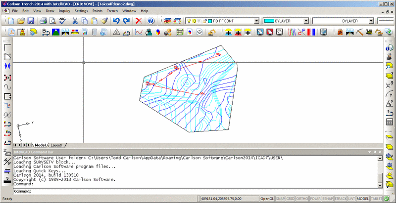
Step 2 (Open Drawing):
From the File menu, choose Open and select
Takeoffdemo2.dwg from the Carlson Projects folder. Save As the
drawing to "takeoffdemo2-A.dwg". Completing this tutorial will
alter the drawing file, by renaming the file from the start, you'll
keep the original file intact (allowing you to run through the
tutorial a second time if desired). This is also a good practice to
keep when working on drawings from 3rd parties.
Step 3 (Make Existing and Design Surfaces):
In order to calculate trench quantities and profiles in this
drawing, we need surfaces for the existing ground and design.
Creating these surfaces is accomplished with Carlson Construction
or Carlson Civil. Switch to either one of these programs at this
time.
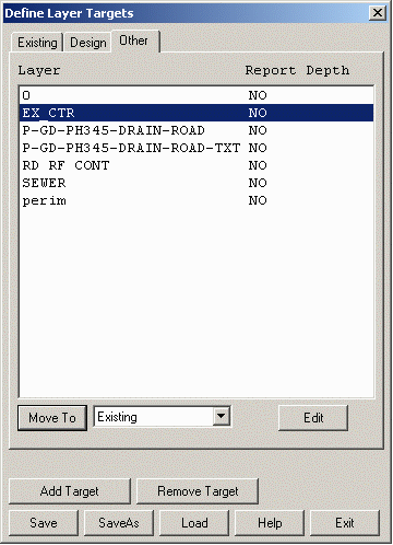
First we need to define the layers of the surfaces. From
Construction, Run TakeOff->Define Surface
Target/Material/Subgrade. In Civil, this command is found under
SiteNET. Then from the tab labeled "Other", highlight "EX_CTR" from
the layer list, pick "Existing" from the Move To list and pick the
Move To button. Next, highlight "RD RF CONT", choose "Design" from
the Move To list and pick the Move To button. Now choose the
Save and then Exit buttons. This assigned layer "EX_CTR" to the
existing ground surface and "RD RF CONT" to the design surface.
Next, let's set the site perimeter. Run TakeOff->Boundary
Polyline->Set Boundary Polyline (under SiteNET in Civil). At the
command line, there is a prompt:
Select boundary polyline:
Pick anywhere along the six sided perimeter polyline in the
drawing.
Now, to make the existing ground surface, run TakeOff->Make
Existing Ground Surface. Then to make the design surface, run
TakeOff->Make Design Surface.
Step 4 (Input Trench Network Data):
Now that we have existing and design surfaces we can switch back to
the Trench module. The trench network data consists of linked
structures where each structure has a name, location (x,y),
invert-in, invert-out and rim elevation. Each structure link has a
pipe size. There are two ways of entering the trench data. When the
drawing contains polylines for the trench lines and labels with the
trench data, then you can use Input Trench From Polyline.
Otherwise, there is the Create Trench Network Structure command
which let's you pick the structure locations and enter the data in
a dialog.
Method 1 (Input Trench Line):
In this example, there is trench data already drawn in the drawing.
Zoom in around the upper right area of trench line by running
View->Zoom->Window and picking two corner points around this
area.
Then run Trench->Input Trench Line and an options dialog
appears. In this case, our Input Method is from a Polyline. We also
want Trench Type as Sewer because there are manhole rim elevations.
Also Prompt For Invert-In Elevations is active since this example
has a manhole with multiple connections with different invert-ins.
And Connected Network is used so that the trench data can be used
by the rest of the trench routines. The Individual Profile option
will only create a profile (.pro) file. Prompt For Pipe Wall
Thickness allows you to enter in the pipe thickness that will be
added to the interior pipe size for accurate volume calculations.
Fill out the dialog as shown and click OK.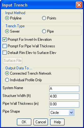 The rest of
the prompting for this command is on the command line as the
program walks through the trench line. For each point in the trench
polyline, the program zooms the drawing to that point. The trench
data can be picked from labels in the drawing. If the drawing
doesn't have labels for the data, then you can enter the
values.
The rest of
the prompting for this command is on the command line as the
program walks through the trench line. For each point in the trench
polyline, the program zooms the drawing to that point. The trench
data can be picked from labels in the drawing. If the drawing
doesn't have labels for the data, then you can enter the
values.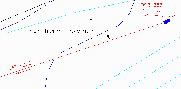 Pick a polyline that represents a
trench reach: Pick the trench
polyline
Pick a polyline that represents a
trench reach: Pick the trench
polyline
Starting Station of trench reach <0.0>: 0.0
For station 0.00 ...
Enter/<Select text of Manhole ID>: Pick the DCB 368 label. (If you had a
drawing without a manhole ID label, then type E for Enter and enter
the ID)
ID: DCB 368
Undo/Enter/<Select text of Invert-in elevation>: Pick the I Out=174 label. (Since this
is the upstream starting manhole, there really isn't a separate
invert-in. So we are using the invert-out).
Invert-In: 174.000
Undo/Enter/<Select text of Invert-out elevation>:
Pick the I Out=174
label.
Invert-Out: 174.000
Undo/Enter/<Select text of manhole rim elevation>:
Pick the R=178.75
label.
Rim: 178.750
For station 201.44 ...
Enter/<Select text of Manhole ID>: Pick the DCB 367 label.
ID: DCB 367
Undo/Enter/<Select text of Invert-in elevation>: Pick the I In=172.85 label.
Invert-In: 172.850
Undo/Enter/<Select text of Invert-out elevation>:
Pick the I Out=172.35
label.
Invert-Out: 172.350
Undo/Enter/<Select text of manhole rim elevation>:
Pick the R=178.5
label.
Rim: 178.500
Undo/Enter/<Select text of pipe size>: Pick the 15" HDPE label.
Pipe Size: 15.0
For station 327.09 ...
Enter/<Select text of Manhole ID>: Pick the CB 347 label.
ID: CB 347
Undo/Enter/<Select text of Invert-in elevation>: Pick the I In=170.540 (CB 367) label.
(This is the invert-in for the connection to the CB 367 structure
that this trench line connects to.)
Invert-In: 170.540
Undo/Enter/<Select text of Invert-out elevation>:
Pick the I Out=166.1
label.
Invert-Out: 166.100
Undo/Enter/<Select text of manhole rim elevation>:
Pick the R=176.5
label.
Rim: 176.500
Undo/Enter/<Select text of pipe size>: Pick the 15" HDPE label.
Pipe Size: 15.0
Another Polyline [<Yes>/No]? N for no.
That completes this trench run and Takeoff draws its own trench
polyline and labels.
Method 2 (Create Trench Network Structure):
The drawing contains another trench polyline and we could use Input
Trench Data From Polyline again. Instead for practice, let's use
the Create Trench Network Structure method. First we need to zoom
to the new trench location. Run View->Zoom->Extents and
then View->Zoom->Window and pick two points for a window
around the lower right trench point (CB 349). Then run
Trench->Create Trench Network Structure. At the command line,
there is a prompt for how to locate the structure position. Choose
Pick.
Locate by pick point, point number or station-offset
[<Pick>/Number/CL]? Pick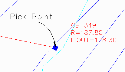 Next,
there is a prompt to pick the position. To get the exact end point
of the trench polyline, use the end point snap. The end point snap
can be turned on by a number of different ways including the
Settings->Object Snap command. In this case, type "end" and then
space or enter. This puts the program in end point snap mode. Now
move the pointer along the trench polyline until the end point snap
icon is at the manhole location and then pick.
Next,
there is a prompt to pick the position. To get the exact end point
of the trench polyline, use the end point snap. The end point snap
can be turned on by a number of different ways including the
Settings->Object Snap command. In this case, type "end" and then
space or enter. This puts the program in end point snap mode. Now
move the pointer along the trench polyline until the end point snap
icon is at the manhole location and then pick.
Pick structure location: end of
(pick point)
Now a dialog appears for entering the structure data. Fill in the
Structure Name as CB 349, the Rim Elevation as 187.8, the
Invert-Out as 178.3, the Structure Width as 4.00 and then pick
OK.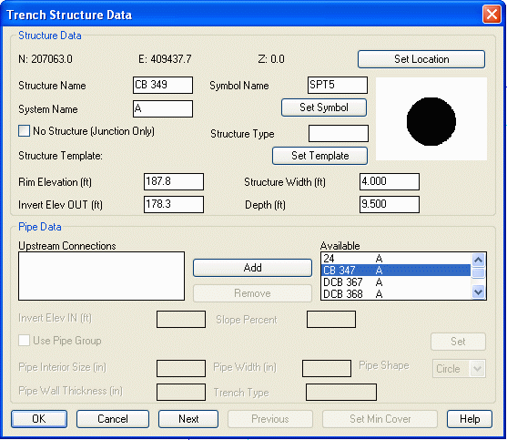 All the structures are now created.
The last step is to link this new structure to the network. We need
to zoom to the next trench location. Run View->Zoom->Extents
and then View->Zoom->Window and pick two points for a window
around the left trench point (CB 347). Now run Trench->Edit
Trench Network Structure and pick either the symbol for CB 347 or
the label. Then a dialog appears with the data for CB 347. From the
Available list, highlight CB 349 and pick Add. This creates a link
from CB 347 to CB 349 and the link data is shown at the bottom of
the dialog. Enter the Invert-In as 171 and the Pipe Size as 24.
Then pick OK.
All the structures are now created.
The last step is to link this new structure to the network. We need
to zoom to the next trench location. Run View->Zoom->Extents
and then View->Zoom->Window and pick two points for a window
around the left trench point (CB 347). Now run Trench->Edit
Trench Network Structure and pick either the symbol for CB 347 or
the label. Then a dialog appears with the data for CB 347. From the
Available list, highlight CB 349 and pick Add. This creates a link
from CB 347 to CB 349 and the link data is shown at the bottom of
the dialog. Enter the Invert-In as 171 and the Pipe Size as 24.
Then pick OK.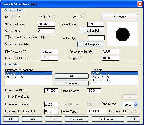
Step 5 (Input-Edit Trench Template):
The Trench Template defines the size of the trench for quantities.
Run Trench->Input-Edit Trench Template. You are first prompted
for a trench template file name. The Trench Template data is stored
in a file that has a .tch extension. Choose the New tab, enter a
file name like trench1 and then pick Open.
Next, there is a dialog for entering the trench dimensions. The
Bottom Offset is the distance from the bottom of the pipe to the
bottom of the trench. The Trench Width is the base width of the
trench. The Vertical Side Height is the height from the bottom that
the side walls are vertical until switching to the cut slope. If
the surface is not reached by the vertical side height, then the
cut slope is used for the rest of the distance to the surface. Edit
Trench Benches allows you to set up to four benches in your trench.
Display Sewer Structure allows you to see your pipe or manhole as
part of the trench. Note: This is for display purposes only,
calculations will be drawn from the pipe size you set in the Trench
Network Structure commands. Add Pipe Diameter To Trench Width will
increase the size of your trench by the diameter of your different
pipe sizes. The Cut Slope can be entered in slope percent, ratio or
degree format. The Backfill materials are optional. They can be
defined from the top or bottom of the trench. Up to three materials
can be entered from the bottom.
Fill out the dialog as shown and pick Save and Exit.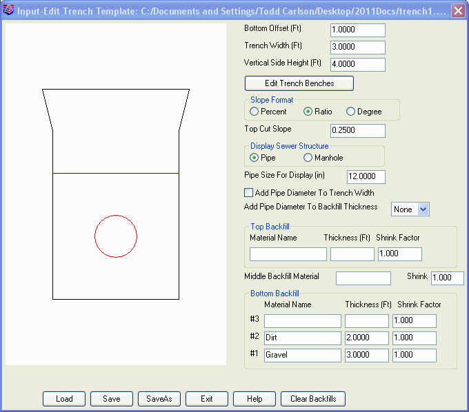
Step 6 (Trench Network Quantities):
To calculate and report the trench quantities, run
Trench->Trench Network Quantities. A dialog sets the report
options. Check on Calculate All Trenches to get the quantities for
the whole network. To get the trench cut volume, check Use Trench
Template For Quantities and pick Set Trench Template and pick
trench1.tch. Also turn on Report Backfill Volumes to use our
backfill material settings from the trench template and Draw Trench
in 3D to create 3D faces of the Trench. Once the dialog is filled
out as shown, pick Setup Depth Zones.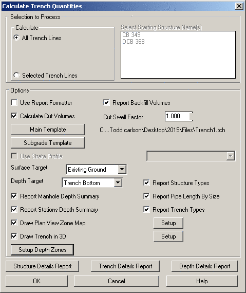 Fill out the depth zones
in the intervals that you are interested in. In this case, use 15,
20 and 25. The depth zones will be colored in the plain view.
Finally, click OK and OK in the main dialog and the report is
shown.
Fill out the depth zones
in the intervals that you are interested in. In this case, use 15,
20 and 25. The depth zones will be colored in the plain view.
Finally, click OK and OK in the main dialog and the report is
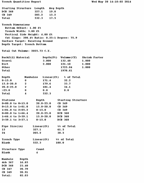
shown.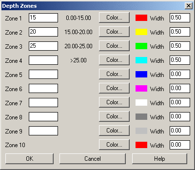 The report includes:
- The structure names at the start of each trench run included in
the report.
- The trench template dimensions.
- The cut volume.
- The backfill volumes.
- The number of manholes and length of trench within each depth
zone.
 The depth
zones in the plain view with Zone Map Color Legend.
The depth
zones in the plain view with Zone Map Color Legend.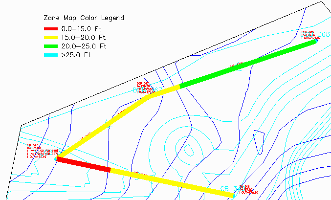
Use "Display > 3D Viewer Window" and window around the 3D faces
to view the Trench in 3D.

Step 8 (Draw Trench Network Profile):
To draw a profile of the trench line, run the Trench->Draw
Trench Network (Profile) command. There is a dialog to select the
starting structure for which trench line to process. Choose DCB
368. Also, there are options whether to draw the existing ground,
design surface and strata surfaces if available. You can also
choose the profile direction to go upstream or downstream. The Save
To Profile File will create a profile (.pro) file for the trench.
Fill out the dialog as shown and pick OK.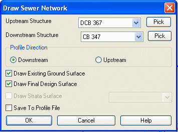 Next the Draw
Profile dialog appears. Set the Horizontal Scale and intervals to
50 and the Vertical Scale and intervals to 25. This will make for
two to one vertical exaggeration for the profile. Click
OK.
Next the Draw
Profile dialog appears. Set the Horizontal Scale and intervals to
50 and the Vertical Scale and intervals to 25. This will make for
two to one vertical exaggeration for the profile. Click
OK.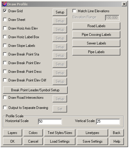 Next, there are prompts at the
command line for the profile grid elevations and profile
location.
Next, there are prompts at the
command line for the profile grid elevations and profile
location.
Bottom Elevation of Profile Grid <150.0>: Press Enter
Top Elevation of Profile Grid <200.0>: Press Enter
Pick Starting Point for Grid <409458.0 , 207303.0>:
Pick a point in a blank area off
to the side of the drawing.
There is a final command line prompt for whether to use the manhole
elevations. Enter Yes which will use the rim elevations defined in
our trench network.
Use manhole elevations from profile [<Yes>/No]?
Y for yes.
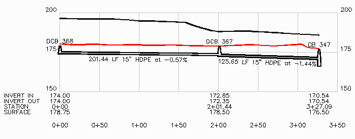
The profile shows the existing ground at the top, then the design
surface and then the trench.