Trench Network Quantities
This command calculates the trench volumes. There has to be a
trench network structure that has been created beforehand and its
data is store in a .sew file whose name is as same as the drawing
name, otherwise you would get an error message like "Error: no data
in sewer network file".
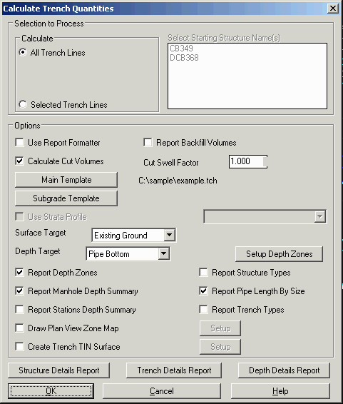
The command loads the trench network data and splits them into
individual trench lines and displays them on the Calculate
Trench Quantities Dialog. You can choose to calculate the
trench volume of one trench line or several trench lines at a time.
You need to set a Main Template in order to calculate
volumes. To create a template, run Trench> Input-Edit Trench
Template. The trench cut volume is multiplied by the Cut Swell
Factor. Surface Target determines the Surface that the bottom of
the trench is compared to, either: the Existing Surface, the
Design, the Existing and Design to minimize cut, or simply to the
Rim Elevations (no surface required). Trench Depths can be reported
by either the bottom of the trench or bottom of the pipe by using
the Depth Target pull-down. If you have Strata Surfaces defined
then the program can calculate cut volumes for a strata you select.
For more comprehensive reports you can customize, click on the
Structure, Trench, and Depth Details Reports buttons. For the
Standard Report, click the OK button.
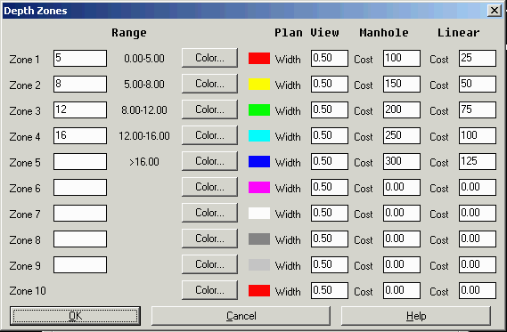
Setup Depth Zones will breakout your trench cut volumes
according to user-defined "depth zones" of the trench. You can also
color the trench in the drawing by these defined zones. The Width
value is used with the Draw Plan View Zone Map for the width of the
trench lines. The Manhole Cost is for reporting the structure cost
by zone depth. The Linear Cost is for reporting the linear cost for
the trench lines by zone depth.
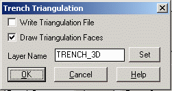
 Create
Trench TIN Surface will create a triangulation surface of the
trench. Under the Setup dialog, the Write Triangulation File option
will have the program prompt for a TIN file to create for the
trench surface. The Draw Triangulation Faces option creates 3D
faces in the drawing on the Layer Name from this dialog. Use "View
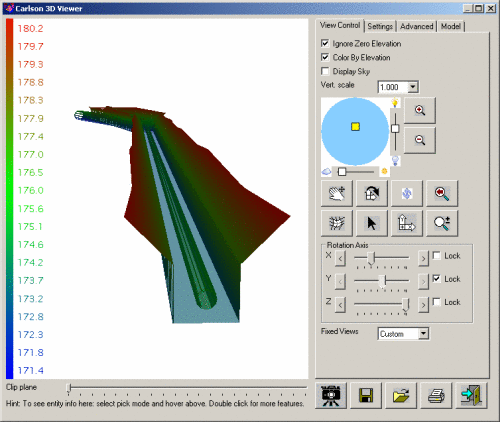
> 3D Viewer Window" to display the new 3D faces in 3D. Note:
Pipes are automatically displayed in 3D from the linework created
in "Draw Trench Network (Plan View)". To turn 3D pipes off in the
viewer, freeze the layer created with "Draw Trench Network (Plan
View)". By default this layer is "SWRNET".
Create
Trench TIN Surface will create a triangulation surface of the
trench. Under the Setup dialog, the Write Triangulation File option
will have the program prompt for a TIN file to create for the
trench surface. The Draw Triangulation Faces option creates 3D
faces in the drawing on the Layer Name from this dialog. Use "View
> 3D Viewer Window" to display the new 3D faces in 3D. Note:
Pipes are automatically displayed in 3D from the linework created
in "Draw Trench Network (Plan View)". To turn 3D pipes off in the
viewer, freeze the layer created with "Draw Trench Network (Plan
View)". By default this layer is "SWRNET".
Click OK to compute the template volumes. Backfill quantities take
into account pipe size. A report would be shown after the
calculation and any depth zone linework and 3D faces will be drawn
in the plan view.
Prompts
Trench Quantities Report
Window
Draw zone map color legend on the screen [Yes/<No>]:
y for Yes
Pick a point for color legend: pick a point away from
site
Legend size <10.00>: Press <Enter> for the default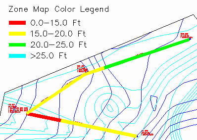
Pulldown Menu Location:
Trench
Prerequisite: Your drawing is open, has been cleaned up and
pre-processed by such commands as Define Layer Target, Set Boundary
Polyline, Make Existing Ground Surface and Make Design Surface.
Trench structure data has been stored in a .sew file, whose name is
as same as the drawing name.
Keyboard Command:
calc_trench