This command provides all of the functionality related to
contouring and creating tin surface models in one routine. Given
data entities that represent the surface, this command creates a
final contour map with labeled, smoothed, and highlighted contours
and/or a surface model that can be saved to a file (to be used in
other areas of the program) or drawn on the screen as triangles or
faces. Eligible data entities include points, inserts, lines,
2d polylines, 3d polylines, elevation text, 3d faces, and points
from ASCII or coordinate (.CRD) files.
Triangulate & Contour has many options which are
defined in the exhibits shown in the following pages. With this
command, you can do any combination of drawing the triangulation
network lines, drawing the contours, drawing triangulation network
3D Faces or lines, writing a triangulation file and storing a
surface file.
In order to force Triangulate & Contour to correctly interpolate elevations between two points that define a grade break in the surface (such as points on a ridge, wall, or road), a breakline must exist between the points. A breakline line can be specified as a 3D polyline or line. In fact, all 3d polylines and lines with elevation are be treated as breaklines.
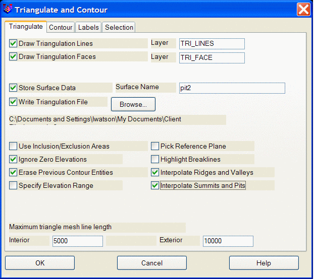
Triangulate Tab
Draw Triangulation Lines
When this option is turned on, the program will draw the triangulation as 3D lines. Specify the layer for these lines in the box to the right.
Draw Triangulation Faces
When this option is turned on, the program will draw each triangle in the triangulation network as a 3D Face. These 3D Faces can then be used in AutoCAD's modeling routines such as HIDE and SHADE or in routines such as 3D Viewer Window, 3D Surface FlyOver and Slope Zone Analysis. Specify the layer for these 3DFaces in the box to the right.Store Surface Data
This option names and creates a surface or surfaces
that are associated with the drawing. The creation of a
surface is necessary in order for the Surface Tools to
function. A Triangulation file must also be specified before
using the Store Surface option.
Write Triangulation File
This option stores the triangulation surface model as an .flt or a .tin file. The .flt file format is a text file depicting the edges in the triangulation network. The .tin file is a new binary file format depicting the triangulation network. The .tin file is much faster and more efficient than the previous .flt file format. The triangulation file/s can be used by several commands such as Volumes By Triangulation, Spot Elevations, and Profile from FLT File. Either type in the file name to create or press the Browse button to select a file name.
Use Inclusion/Exclusion Areas
When this box is activated, the program will later prompt you for inclusion and exclusion polylines which are used to trim the contours. The inclusion and exclusion polylines must be closed polylines and must be drawn before starting Triangulate & Contour. Only the parts of the contour lines that are within the inclusion polylines will be drawn. For example, an inclusion could be the perimeter of the site. The parts of contour lines that are inside the exclusion polylines are not drawn. Exclusion polylines can be used for areas where you don't want contours such as within buildings.
Ignore Zero Elevations
When activated, this setting will filter out all data points at an elevation of zero from the data set.
Erase Previous Contour Entities
When activated, this setting will erase previously drawn contour entities.
Specify Elevation Range
The program will automatically contour from the lowest elevation in the data set up to the highest at the increment specified in Contour Interval. If you would like to manually set the range over which to contour, select this option.
Pick Reference Plane
The triangulation network is based on the x,y position of the points. This option allows you to contour an overhang or cliff by changing the reference plane to a side view. The reference plane can be specified by first using the Viewpoint 3D command and then using the View option, or you can specify three data points on the cliff (two along the bottom and one at the top).
Highlight Breaklines
This option highlights breaklines in the triangulation network by drawing the triangulation lines along breaklines in yellow.
Interpolate Ridges and Valleys
This option creates additional triangulation in a ridge or
valley situation to more accurately define the feature during
surface modeling operations. This option would commonly be
used when creating a surface model from existing contours, since it
replaces the need to manually draw 3d polylines along ridges and
valleys.
Interpolate Summits and
Pits
This option creates additional triangulation in a summit or pit situation to more accurately define the feature during surface modeling operations. This option would commonly be used when creating a surface model from existing contours.
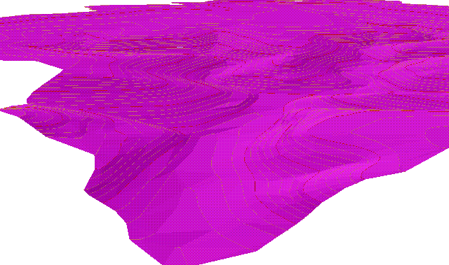
Before: Surface made from an existing contour map.
Note the flat spots in the bottom of the valley when Interpolate
Ridges and Valleys is disabled.
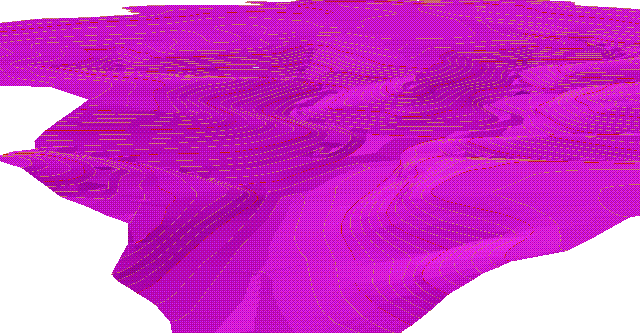
After: The same surface with
Interpolate Ridges and Valleys enabled.
Max Triangle Mesh Line Length
This value limits the length of the triangulation network lines. Any triangulation line that exceeds this limit will not be drawn or included in contouring. This allows you to avoid abnormally long triangulation lines where you have relatively too few data points and on the outskirts of your data points. The Exterior value applies to triangulation lines around the perimeter of the triangulation area and the Interior value applies all the other triangulation lines. Generally you would have the exterior value larger than the interior.
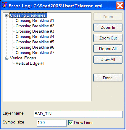
Error Log
The following dialog box appears when the Triangulate &
Contour routine finds a conflict between breaklines or other
surface entities. The type of conflict is identified, and
when an item is chosen, a highlighted arrow is temporarily placed
in the drawing to indicate the exact location of the specific
conflict. Crossing Breaklines indicates that the intersection
of two entities has two differing elevations. Vertical Edges
indicates that two entities or vertexes of differing elevations
have the same xy location, thus forming a vertical
plane.
Contour Tab
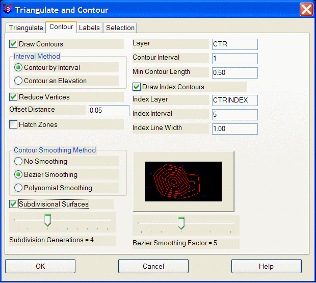
Draw Contours
When this box is checked, the program will draw contour lines after triangulating. Otherwise, only the designated triangulation operations are performed. Specify the layer for contours in the edit box to the right.
Contour by Interval or Contour an Elevation
Select whether to contour by interval (ie: every 10 feet) or to
contour a certain elevation. The elevation option allows you to
contour specific values. For example, if you want just the 100ft
contour, then select elevation and enter 100. The default mode is
by interval.
Contour Interval
Specify the interval to contour. Note: If the above option is set to Contour an Elevation, then this field is used to specify the elevation to contour.
Minimum Contour Length
Contour lines whose total length is less than this value will not be drawn.
Reduce VerticesThis option attempts to remove extra vertices from the contour polylines which has the advantages of a faster drawing and smaller drawing size. Default is ON
Offset Distance
When the Reduce Vertices option is enabled, This value is the
maximum tolerance for shifting the original contour line in order
to reduce vertices. The reduced contour polyline will shift no more
than this value, at any point, away from the original contour line.
A lower value will decrease the number of vertices removed and keep
the contour line closer to the original. A higher value will remove
more vertices and allows the contour line to shift more from the
original.
Hatch Zones
When activated, this option will allow you to hatch the area between the contours sequentially. A secondary dialog will load allowing the user to specify the hatch type and color.
Draw Index Contours
This option creates highlighted contours at a specified interval. When enabled, the fields for Index Layer, Index Interval and Index Line Width are activated.
Contour Smoothing Method
Select the type of contour smoothing to be performed. Bezier smoothing holds all the contour points calculated from the triangulation and only smooths between the calculated points. Polynomial smoothing applies a fifth degree polynomial for smooth transition between the triangulation faces. The smoothing factor described below affects the smoothing bulge.
Bezier Smoothing Factor
The contour preview window shows you an example of how much smoothing can be expected at each setting. Sliding the bar to the left results in a lower setting which have less looping or less freedom to curve between contour line points. Likewise, moving the slider to the right results in a setting that increases the looping effect.This option causes each triangle in the triangulation surface model to be subdivided into an average of three smaller triangles per subdivision generation, with the new temporary vertices raised or lowered to provide smoother contours. More generations increases the smoothness of the algorithm at a cost of increased processing time. If Straight Lines are chosen as the contouring drawing method, then the contours are guaranteed never to cross. The original points of the surface model are always preserved. These modifications to the surface model are only for contouring purposes and are not written to the triangulation (.FLT) file or inserted into the drawing. If some contour movement is too small for appearance's sake, consider enabling Reduce Vertices.
Labels Tab
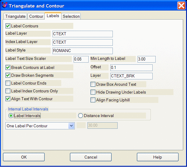
Label Contours
When activated, contours will be labeled based on the settings below.
Label Layer
Specifies layer name for intermediate contour labels.
Index Label Layer
Specifies layer name for index contour labels.
Label Style
Specifies the text style that will be used for the contour label text.
Label Text Size Scaler
Specifies the size of the contour labels based on a multiplier of the horizontal scale.
Min Length to Label
Contours whose length is less than this value will not be labeled.
Break Contours at LabelWhen checked, contour lines will be broken and trimmed at the
label location for label visibility. When enabled, the Offset
box to the right activates. The Offset determines the gap
between the end of the trimmed contour line and the beginning or
ending of the text.
Draw Broken Segments
When checked, segments of contours that are broken out for label visibility will be redrawn as independent segments. Specify the layer for these broken segments in the box to the right of this toggle.
Label Contour Ends
When checked, contour ends will be labeled.
Draw Box Around Text
When checked, a rectangle will be drawn around contour elevation labels.
Label Index Contours Only
When checked, only the index contours will be labeled.
This option is active only when "Draw Index Contours" has been
selected in the Contour tab of the main dialog.
Hide Drawing Under Labels
This option activates a text wipeout feature that will create
the appearance of trimmed segments at the contour label, even
though the contour is fully intact. This feature provides the
user with the best of both worlds; you have clean looking contour
labels, and the contour lines themselves remain contiguous.
This feature will also hide other entities that area in the
immediate vicinity of the contour label.
Align Text with Contour
When checked, contour elevation labels will be rotated to align
with their respective contour lines. This option also
activates the Align Facing Uphill feature explained below.
When checked, contour elevation labels will still be rotated to
align with their respective contour lines, but the labels will be
flipped in such a manner that the bottom of the text label will
always be toward the downhill side of the contours. So as the
labels are read right side up, you are always facing
uphill.
Internal Label Intervals
Choose between label intervals or distance interval. Label intervals will label each contour with a set number of labels. Distance interval lets you specify a distance between labels.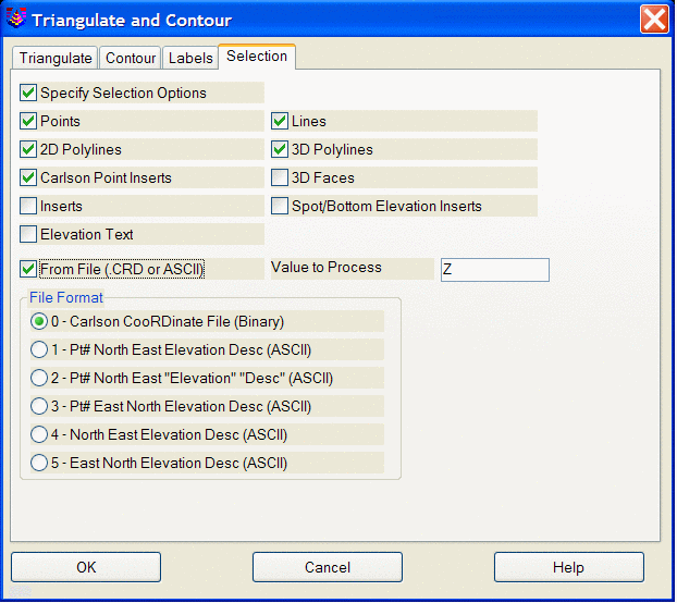
Specify Selection Options
When checked, this allows you to control what type of entities Triangulate & Contour uses.
Points, 3D Polylines, 2D Polylines, Lines, Inserts are standard AutoCAD entities types.
Spot/Bottom Elevation Inserts include text entities that start with 'X'.
From File allows you to triangulate from the points in a coordinate (.CRD) or ASCII file.
 Label Contour Ends
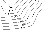 Align Text With Contour ON
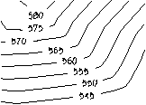 Align Text With Contour OFF
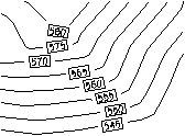 Draw Box Around Text
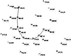
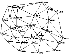 Triangulation network without contouring
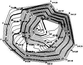
Pull-Down Menu Location: Tools-> Surface Tools
Prerequisite: Data points of the surface
Keyboard Command: tri