Make Existing Ground Surface
This command makes the triangulation models for the existing ground
surface. There are three surfaces that are created: initial
original ground (og), original ground after applying subgrade zones
(ze), and original ground after subgrade zones and topsoil removal
(ex). These surface files are automatically named as
"filename-og.tin", "filename-ze.tin" and "filename-ex.tin"
respectively. The "filename" is set to the name of the current
drawing (dwg) file. Also, the file extension will be .tin for the
binary format triangulation and .flt for the ASCII format
triangulation. This file format is set in
Configure->Takeoff.
The surface is built using 3D entities in the drawing on the layers
define in Define Layer Target/Material/Subgrade command. Also, the
surface elevation for any drillholes are used for the model. The
subgrade zones are defined in the Define Layer
Target/Material/Subgrade command. If there aren't any subgrade
zones for the Existing surface, then the original ground after
subgrades surface with be the same as the initial original ground
surface. The topsoil removal depths and areas are set with the
commands in the Topsoil Removal/Replacement sub-menu. The topsoil
removal areas will lower the ground surface by the topsoil depth.
If there aren't any topsoil removal areas, then the original ground
after subgrade and topsoil surface will be the same as the original
ground after subgrade surface.
Before running this command, the layer names for the entities on
the Existing layer target must be set in the Define Layer
Target/Material/Subgrade command. Also these entities must be at
their proper elevations. The entity elevations can be reviewed
using commands from the Inquiry menu and the elevations can be
assigned if needed using command from the Elevate menu. Another
prerequisite is that the Boundary Polyline must be set for the
site. If the boundary has not been set, the following error message
will appear.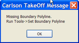 If this error message appears, run
the "Set Boundary Polyline" command and pick the CLOSED polyline
representing the boundary of the site.
If this error message appears, run
the "Set Boundary Polyline" command and pick the CLOSED polyline
representing the boundary of the site.
When the program finds errors in the existing entities, a Data
Error Log dialog reports these errors. Three types of conflicts are
reported: Crossing Breaklines, Vertical Edges, and Breakline
T-Intersections. Crossing Breaklines indicates that the
intersection of two entities does not have a common elevation.
Vertical Edges indicates that two entities or vertices of differing
elevations have the same x-y location, thus forming a vertical
plane. Breakline T-Intersections indicates that a 3d entity is
abutting another entity, but the second entity doesn't have a
vertex at the point of intersection. Each type of conflict is
listed in its own category.
The Data Error Log shows the amount of elevation difference at each
error. You can use the Data Error Log to review, report and draw
markers at these error locations. Then you can exit the Data Error
Log and fix the data errors with the commands in the Elevate menu
or other drafting tools. After these errors are fixed, you can run
Make Existing Ground Surface again.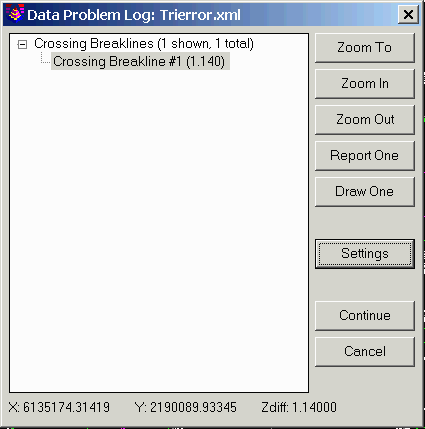 Clicking to the "plus" sign
beside a category will display the individual conflicts within that
category. When a line item error is selected, a highlighted arrow
is temporarily placed in the drawing to indicate the exact location
of the specific conflict. Zoom functionality allows the user to
more closely inspect the specific problem area, and if needed a
marker can be drawn or a report generated for an individual
conflict or conflicts.
Clicking to the "plus" sign
beside a category will display the individual conflicts within that
category. When a line item error is selected, a highlighted arrow
is temporarily placed in the drawing to indicate the exact location
of the specific conflict. Zoom functionality allows the user to
more closely inspect the specific problem area, and if needed a
marker can be drawn or a report generated for an individual
conflict or conflicts.
Zoom To pans the drawing
to move the selected conflict to the center of the screen. The zoom
functions are only active when a single line item is selected.
Zoom In zooms in on the highlighted area for closer
inspection. Multiple picks
on the zoom button will increase the magnification.
Zoom Out zooms out away from the highlighted area.
Report All/One toggles between One and All depending
whether a single line item conflict or a category is selected from
the error log. An error report is generated listing the x-y
position and the elevation difference of the entities in
conflict.
Draw All/One toggles between One and All depending
whether a single conflict or a category is selected from the list.
This option draws an "X" symbol at each selected conflict. The
layer and size of the symbol is controlled in the fields below.
Continue closes the Error Log and proceeds with the
contouring operation.
Settings has controls for the tolerances for error reporting
and for the Layer Name and Symbol Size to use with the Draw
function.
Keyboard Command: mk_exist_tin
Prerequisite: a boundary polyline and elevated entities on
the Existing layer target