Offset 3D Polyline By Grade Table
This command creates a 3D polyline that is offset from a reference
3D polyline using the distances and slopes from a Grade Table file.
This command provides a simple and easy way to handle complex
offsets for features like bottom of ditch polylines offset from the
road edge-of-pavement in a road design with transitions.
The Grade Table defines the slopes and offset distances at
different stations along the reference polyline. Slopes and offsets
for polyline segments between defined stations in the list are
interpolated. For example, if the distance at station 0 is 10 and
the distance at station 100 is 14, then the offset distance for a
polyline vertice at station 50 would be 12. Then slopes and
distances are interpolated separately. So if there is a slope
change at a station but the distance doesn't change at that
station, then you only need to make an entry in the table with the
station and slope and leave the distance blank.
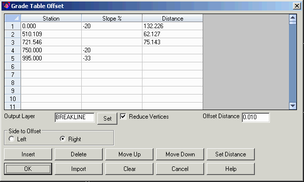
The Output Layer is used for the offset 3D polyline that is
created. The Side To Offset controls the offset direction
from the reference polyline. The Reduce Vertices
is used to reduce the number of vertices in
the offset polyline. The Offset Distance is the maximum amount that the
polyline can move horizontally when removing a point. To not
reduce vertices, set this Offset Distance to zero.
The Set Distance function has several methods for filling
out the distance in the table.
Polyline method: prompts to pick the reference and
target polylines and then figures the different distances between
them. This method applies when there is a 2D polyline for the
target location of the 3D offset.
Profile method: prompts for the reference 3D polyline and a
target profile. The slope must already by defined in the Grade
Table. This method uses the elevation difference between the
reference 3D polyline and a profile plus the slope to fill out the
distances.
Surface method: prompt for the reference 3D polyline and the
target surface. The slope must already by defined in the Grade
Table. This method finds the intersection of the surface from the
reference 3D polyline at the slope to fill out the distances.
Section method: prompt for the reference 3D polyline and a
cross section file. The reference polyline should be at offset zero
of the cross sections. The slope must already by defined in the
Grade Table. This method finds the intersection of the cross
section from the reference 3D polyline at the slope to fill out the
distances.
The Import function reads in station, slope and distance
data into the table. The data can come from either a text file,
drawing graphics or superelevation file. For the text file, the
format should have station, slope% and distance separated by a
delimiter such as a comma. For the drawing graphics, the import
reads a polyline on a superelevation diagram grid to set the
transition slopes. For superelevation file method, the import reads
the transition slopes from a .sup file.
Pulldown Menu Location: Roads
Prerequisite: 3D Polyline
Keyboard Command: tgtoffset