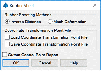
This command adjusts an image to fit control points. This image
adjustment applies when the image distortion varies and requires
more than a single translate, rotate and scale transformation. This
command changes the image file. The original image file is backed
up to a separate file with a .bak extension.
There are two methods to model the adjustment from the control
points. The Inverse Distance method weights the delta x/y from each
control point as the inverse of the distance to the control point.
This way the closer control points have a higher weight. The Mesh
Deformation uses an affine transformation. The control points can
be either loaded from a file stored previously by Rubber Sheet, or
by screen picking. With picking, the control points are defined by
screen picking a point on the image and then the point to move this
point on the image to. In the example shown here, the roads in the
image don't line up with the road linework. After picking the road
points on the image and the corresponding points on the linework,
the image is adjusted to fit the road linework. The Output Control
Point Report generates a report of the control point
coordinates.
Image before Rubber Sheet showing control
pointsImage
after Rubber Sheet
Prompts
Pick origin of control point 1:pick point 1 Pick destination of control point 1:pick point 2 Pick origin of control point 2:pick point 3 Pick destination of control point 2:pick point 4 Pick origin of control point 3 (Enter to end):pick point
5 Pick destination of control point 3:pick point 6 Pick origin of control point 4 (Enter to end):pick point
7 Pick destination of control point 4:pick point 8 Pick origin of control point 5 (Enter to end):press
Enter
Pulldown Menu Location: Raster Keyboard Command: rasrubber Prerequisite: an Image
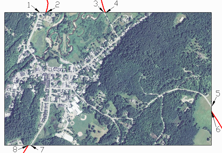 Image before Rubber Sheet showing control
points
Image before Rubber Sheet showing control
points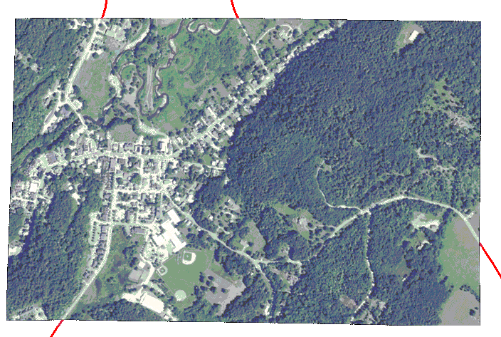 Image
after Rubber Sheet
Image
after Rubber Sheet