Digitize
Digitizer Setup
Digitizing is the act of inputting
data into the computer by tracing the data from a plan sheet. You
need to have a digitizer board, puck, Carlson Takeoff, your
computer and your plan to do digitizing. Wintab
is a digitizer driver that lets you to use the digitizer cursor as
both a digitizer cursor and a mouse. You need to install Wintab
when you install Carlson Takeoff. Wintab can be downloaded from
GTCO web site: http://www.gtcocalcomp.com/supportgtcosoftware.htm.
Select the driver version that suits the type of your digitizer
board well.
After you installed Wintab driver
on your computer, you set up you digitizer to the correct point
mode. In Windows 2000/XP, go to Start->Settings->Control
Panel->TabletWorks, high light the 16-Btn Cursor, and select Mouse as the Pointing Mode, which lets the digitizer
cursor moves relatively to the screen coordinates. This step is
indicated in the following TabletWorks Control Panel
dialog.
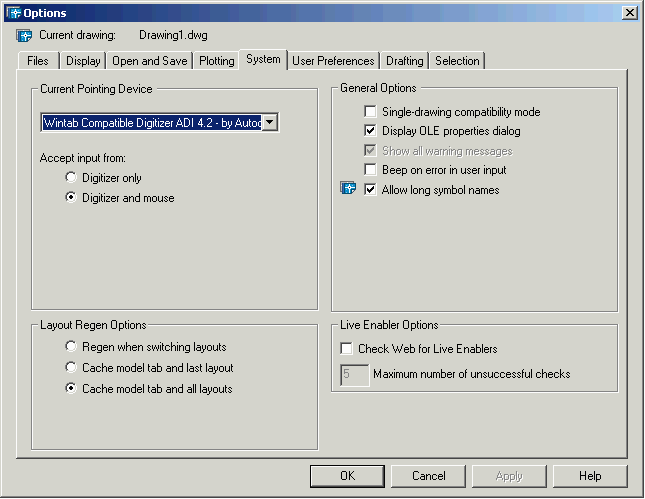
The next is to set up the pointing
device in Carlson Takeoff. Open up Takeoff and go to pull-down
Settings->Preferences, click tab System, select Wintab Compatible Digitizer as
Current Pointing Device,
and set the Accept input
from to Digitize and
mouse. Please refer to the following Options dialog.
Now, you are ready to use your
digitizer. On the bottom of the screen, there is a tray icon TABLET
on the right side of MODEL. You can use accelerator key
F4 to toggle on/off the
tablet.
Puck Layout
The 16-button puck can be used as
either a mouse or a digitizer. It's very important to understand
how the 16 buttons are mapped in both modes.
Mouse Mode:
When the tablet is off, the puck is
in Mouse Mode. The top-left button is the left mouse click, and the
top-right button is the right mouse click. The labels on the other
buttons do not mean anything. All buttons are mapped as same as the
buttons of the default pointing device in AutoCad . Please refer to
AutoCad Reference manual for further information.
Digitize Mode:
When tablet has been calibrated and
is on, the puck is in digitize mode. It is mapped as a small
keyboard, which enables you to enter numerous values such as
elevation, thickness and offset etc., and also provide you some
functionality to digitize various entities. Currently there are two
puck layouts in Takeoff, shown in the figure below. After you
install Carlson Takeoff and finish setting up the digitizer, you go
to the pull-down menu Digitize->Puck Layout to select a
16-button puck layout. A button mapping would be created and
Takeoff would recognize the buttons as represented.
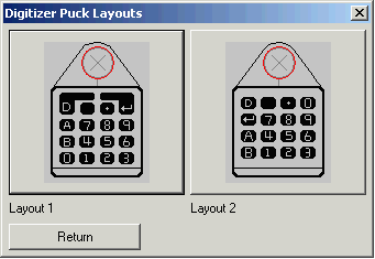
Layout 1 is Carlson Puck Layout,
which is the most common layout used in Carlson Takeoff. Layout 2
is for users who don't have a Carlson Puck. If your puck is
different than these two layouts, please contact Technical Support
for help setting the mapping for your 16 button puck.
Prompts:
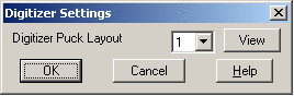
Digitizer Settings
Dialog
Specify the Digitizer Puck Layout to layout 1 or 2
Keyboard Command:
dig_config
Pull-Down Menu Location:
Digitize
Prerequisite:
Have a digitizer board and a puck connected to your computer, and
have Wintab driver installed. The digitizer has been correctly set
up.
Tablet Calibrate
Function:
You can calibrate the
tablet/digitizer in one of two ways: Known Reference Points or Drawing Scale with New Reference
Points. Reference points are the foundations of whatever
data you digitize into the computer. Takeoff bases everything from
drawing location to drawing scale on the reference points you
digitize.
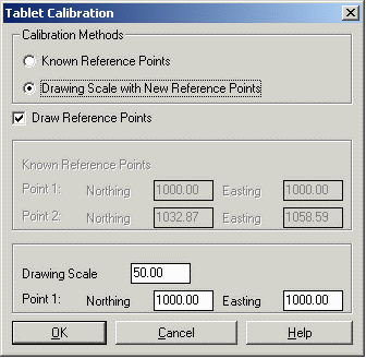
Drawing Scale with New Reference Points
method is very convenient when you don't know the precise
coordinates of the entities on your drawing. As long as your can
obtain the drawing scale from your plan, this method can establish
a coordinate system relative to the position of the plan on the
digitizer board. In addition to the drawing scale, you are required
to enter a random coordinate for the first reference point, the
default coordinate is (1000,1000). Takeoff would computer the
coordinate of the second reference point that you pick based on the
first point. The coordinates of these two reference points would be
saved and will be display on the Tablet Calibration Dialog next time
when you calibrate the tablet, so you can digitize back to the
previous coordinates using Know
Reference Points method if you are working on the same
drawing, though you might have moved or rotated your drawing on the
digitize board..
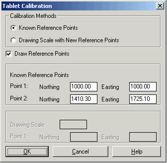
If you know the precise coordinates
of two points, you can select Known Reference Points method, which
establishes a coordinate system that is exactly match the
coordinates in the field or on your drawing. Furthermore, Takeoff
saves the coordinates of the two reference points from previous
calibration and displays them on the Tablet Calibration Dialog next time
when you calibrate the tablet. If you want to continue to work on
the same drawing, you can use the Know Reference Points method with the
saved coordinates to digitize back to your previous coordinates
although you might have moved or rotated your drawing on the
digitizer board.
For accurate takeoff calculations, choose two points that can be
easily found in the field and are farther apart rather than closer
together.
Prompts:
Tablet Calibration Dialog
Specify the Calibration Methods. If you select Drawing Scale
method, enter the drawing scale and the coordinate of the first
reference point. Otherwise enter the exact coordinates of the first
and second reference points.
Pick first reference
point:
pick a point on the drawing
Pick second reference
point:
pick another point on the drawing
Keyboard Command:
digsetup
Pull-Down Menu Location:
Digitize
Prerequisite:
Have a digitizer board and a puck
connected to your computer, and have Wintab driver installed. The
digitizer has been correctly set up.
Tablet On
Function:
Executes AutoCad's TABLET command
to set the tablet on. Refer to the AutoCad Reference manual for
further information.
P.S. Function key [F4] can toggle on/off tablet.
Keyboard Command:
tablet
Pull-Down Menu Location:
Digitize
Prerequisite:
Have a digitizer board and a puck
connected to your computer, and have Wintab driver installed. The
digitizer has been correctly set up.
Tablet Off
Function:
Executes AutoCad's TABLET command
to set the tablet on. Refer to the AutoCad Reference manual for
further information.
P.S. Function key [F4] can toggle on/off tablet.
Keyboard Command:
tablet
Pull-Down Menu Location:
Digitize
Prerequisite:
Have a digitizer board and a puck
connected to your computer, and have Wintab driver installed. The
digitizer has been correctly set up.
Save Tablet Calibration
Function:
This command saves current tablet
calibration to a file. You are prompted to enter a file
name.
Keyboard Command:
tablet1
Pull-Down Menu Location:
Digitize
Prerequisite:
Have a digitizer board and a puck
connected to your computer, and have Wintab driver installed. The
digitizer has been correctly set up. Have done tablet calibration
for current drawing.
Load Tablet
Calibration
Function:
This command restores the tablet
calibration parameters from a file and load it into the current
drawing. You are prompted to specify a file name.
Keyboard Command:
tablet2
Pull-Down Menu Location:
Digitize
Prerequisite:
Have a digitizer board and a puck
connected to your computer, and have Wintab driver installed. The
digitizer has been correctly set up. The calibration file should be
associated to the current drawing, and the current drawing
shouldn't have been moved on the digitizer board since last
calibration.
Point
Function:
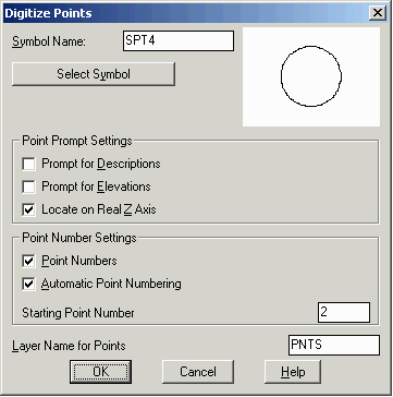
This command allows you to digitize
individual points one at a time. The first time it prompts you the
Digitize Points Dialog for
entering point symbol styles, point prompt settings and number
settings, starting point number and layer name. If you want to
enter the elevation and description for each point, select
Prompt for Descriptions and
Prompt for Elevations.
After having digitized a point, you can continue to digitize next
point by picking the point on the drawing. The command defaults to
the last layer name, point symbol, elevation, description and the
last point number plus 1. If you have finished digitizing points,
press
Enter to
finish.
Prompts:
Digitize Points Dialog
Specify a layer name and select the point symbol, point prompt
settings and number settings.
Pick point to create (Enter to
end): pick a point on the drawing
Select/<Enter Point Elevation
<>>: enter the elevation or
type <Select> to select the elevation text on the
screen
Enter Point Description
<>: enter the point
description
Result like "N: 1231.16 E: 1099.17 Z: 30.00" would be
display on the command line, and a point would be drawn on the
screen with the text of its number, elevation and description.
Pick point to create (Enter to
end):
pick next point or press Enter to finish digitizing
points
Keyboard Command:
dig_pt
Pull-Down Menu Location:
Digitize
Prerequisite:
Have a digitizer board and a puck
connected to your computer, and have Wintab driver installed. The
digitizer has been correctly set up. Have done tablet calibration
for current drawing.
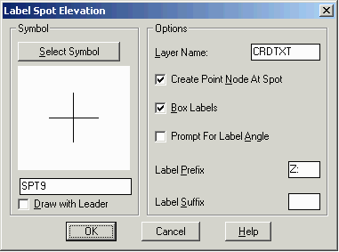
Spot Elevation
Function:
This command allows you to label
points with their elevation. The point can either be digitized from
a drawing, picked on a screen or specified by a point number. The
command first prompts you the Label Spot Elevation Dialog for
entering layer name, label prefix and suffix and symbol types etc.
Click OK to start. After specifying the point, the command prompts
you to enter the elevation if its elevation is unknown and then
pick an angle from the location of the point to label the
elevation. You can repeat labeling points until you press
Enter to finish.
Prompts:
Label Spot Elevation Dialog
Specify a layer name, label prefix and suffix and select the spot
symbol.
Point to Label ?
Pick point or point number:
2 (enter a
point number)
PointNo. Northing(Y) Easting(X)
Elev(Z) Description
2
1231.16
1099.17 30.00
bb
Note:
if the point number you entered is not in the drawing, you will be
prompted again to pick point or enter a point number.
Elevation
<30.000>: press enter
Pick angle for
label: pick an angle from the spot
Point to Label (ENTER to
End)?
Pick point or point number:
pick a point
on the drawing
Elevation
<0.000>: enter elevation
Pick angle for label:
pick an angle
from the spot
Point to Label (ENTER to
End)?
Pick point or point
number: press
enter to finish
Keyboard Command:
labspot
Pull-Down Menu Location:
Digitize
Prerequisite:
Have a digitizer board and a puck
connected to your computer, and have Wintab driver installed. The
digitizer has been correctly set up. Have done tablet calibration
for current drawing.
2D Polyline
Function:
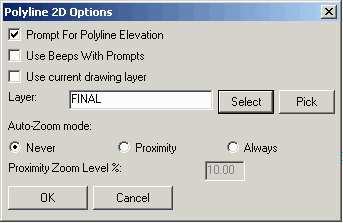
2D polyline is a line of connected
points that have the same elevation. This command lets you digitize
a 2D polyline by picking points along the lines on the drawing. It
prompts you first the Polyline 2D
Options Dialog for entering the layer name. Prompt For Polyline Elevation option
allows you to enter the elevation for each polyline, otherwise all
2D polylines have 0.0 elevation. Auto-Zoom mode would automatically zoom
the display to center around the last point when you get near the
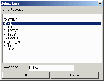
edge of the screen while picking points. There are three ways to
enter a layer name, Use current
drawing layer, Select from a list of layer name, or
Pick an entity on the
screen to get its layer name. While digitizing a polyline, the
command keeps prompting you to pick next point until your
press Enter to finish digitizing, or
press A on the puck or
enter Close on the keyboard
to close the polyline on itself . If you make a mistake,
press B on the puck or
enter Undo on the keyboard
to remove the mistake and then continue to digitize. After
finishing a polyline, the command prompts your to digitize another
polyline until you press B
or enter No.
Prompts:
Polyline 2D Options Dialog
Enter the layer name and select the options of Prompt For Polyline
Elevation and Auto-Zoom mode etc.
Enter default elevation
<0.00>: 100
First
point: pick a point on the drawing using
puck
Segment length: 0.00, Total length: 0.00
Close[A]/Undo[B]/Pick next point
(Enter to end): pick next point
Segment length: 119.03, Total length: 119.03
Close[A]/Undo[B]/Pick next point
(Enter to end): pick next point
Segment length: 121.76, Total length: 240.80
Close[A]/Undo[B]/Pick next point
(Enter to end): pick next point
Segment length: 115.23, Total length: 356.03
Close[A]/Undo[B]/Pick next point
(Enter to end): press enter to finish digitizing or press A
to close the polyline
Digitize Another FINAL Polyline
[Yes(A)/<No(B)>]? press A on the puck or enter Yes on the
keyboard to digitize next 2D polyline, press B on the puck or enter
No on the keyboard to finish digitizing 2D
polyline.
Keyboard Command:
dig_2dp
Pull-Down Menu Location:
Digitize
Prerequisite:
Have a digitizer board and a puck
connected to your computer, and have Wintab driver installed. The
digitizer has been correctly set up. Have done tablet calibration
for current drawing.
3D Polyline
Function:
3D polyline is a line of connected points that have various
elevations, and the slope between points is constant. It can be
used in defining pads, excavations, drainage ditched and slopes
from proposed design features to meet existing site conditions.
This command lets you digitize a 3D polyline by picking points
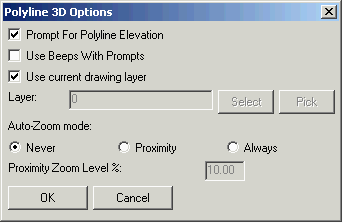
along the lines on the drawing. It prompts you first the
Polyline 3D Options Dialog
for entering the layer name.
Prompt For Polyline Elevation option
allows you to enter the elevation for each point you pick. If you
don't select this option, all points have 0.0 elevation and you get
a 2D polyline. There are four ways to enter elevations: known
elevation of the point, slope from previous point, ratio from
previous point and degree from previous point. You can choose one
of the methods between picking points.
Auto-Zoom mode would automatically zoom
the display to center around the last point when you get near the
edge of the screen while picking points. While digitizing a
polyline, the command keeps prompting you to pick next point until
your
press Enter to finish digitizing, or
press A on the puck or
enter Close on the keyboard
to close the polyline on itself . If you make a mistake,
press B on the puck or
enter Undo on the keyboard
to remove the mistake and then continue to digitize. After
finishing a polyline, the command prompts your to digitize another
polyline until you
press B
or
enter No.
Prompts:
Polyline 3D Options
Dialog
Enter the layer name, toggle on Prompt For Polyline Elevation and
select the Auto-Zoom mode.
First point:
pick a point on the
drawing
Elevation <0.00>:
12 (enter the
elevation)
Z: 12.00, Hz dist: 0.00, Slope dist: 0.00, Slope: 0.0% Ratio:
0.0:1
Close[A]/Undo[B]/Pick next point
(Enter to end): pick a point on the drawing
Slope/Ratio/Point/Degree/<Elevation>
<0.00>: S (switch to entering Slope)
Ratio/Point/Elevation/Degree/<Slope>
<-8.24>: 12 (enter the slope)
Z: 29.47, Hz dist: 145.56, Slope dist: 146.61, Slope: 12.0% Ratio:
8.3:1
Close[A]/Undo[B]/Pick next point
(Enter to end): pick a point on the drawing
Ratio/Point/Elevation/Degree/<Slope>
<-15.31>: R (switch to entering Ratio)
Slope/Point/Elevation/Degree/<Ratio>
<-6.53>: 23 (enter the ratio)
Z: 37.83, Hz dist: 192.45, Slope dist: 192.63, Slope: 4.3% Ratio:
23.0:1
Close[A]/Undo[B]/Pick next point
(Enter to end): pick a point on the drawing
Slope/Point/Elevation/Degree/<Ratio>
<-5.44>: D (switch to entering Degree)
Slope/Ratio/Elevation/Point<Degree(dd.dddd)>
<0.0000>: 22 (enter the degree)
Z: 121.04, Hz dist: 205.94, Slope dist: 222.11, Slope: 40.4% Ratio:
2.5:1
Close[A]/Undo[B]/Pick next point
(Enter to end): pick a point on the drawing
Slope/Ratio/Elevation/Point<Degree(dd.dddd)>
<0.0000>: P (switch to entering Point)
Slope/Ratio/Elevation/Degree/<Point>
<0.00>: 34 (enter Z value of the point)
Z: 34.00, Hz dist: 206.05, Slope dist: 223.68, Slope: -42.2% Ratio:
-2.4:1
Close[A]/Undo[B]/Pick next point
(Enter to end): press Enter to finish digitizing current
polyline, or enter A to close the polyline
Digitize Another 0 Polyline
[Yes(A)/<No(B)>]? press A on the puck or enter Yes on the
keyboard to digitize next 3D polyline, press B on the puck or enter
No on the keyboard to finish.
Keyboard Command:
dig_3dp
Pull-Down Menu Location:
Digitize
Prerequisite:
Have a digitizer board and a puck connected to your computer, and
have Wintab driver installed. The digitizer has been correctly set
up. Have done tablet calibration for current drawing.
Perimeter
Function:
Perimeter is a 2D polyline that all
points on it have the same elevation. It can be used as boundary
polyline of your targets on your drawing. This command allows you
to digitize a perimeter by picking points on the drawing. While
digitizing a polyline, the command keeps prompting you to pick next
point until your press
Enter to finish digitizing,
or press A on the puck or
enter Close on the keyboard
to close the polyline on itself . If you make a mistake,
press B on the puck or
enter Undo on the keyboard
to remove the mistake and then continue to digitize. After
finishing a perimeter, the command prompts your to digitize another
polyline until you press B
or enter No.
Prompts:
First point:
pick a point on the drawing using
puck
Segment length: 0.00, Total
length: 0.00
Close[A]/Undo[B]/Pick next point
(Enter to end): pick next point
Segment length: 104.27, Total length: 104.27
Close[A]/Undo[B]/Pick next point
(Enter to end): pick next point
Segment length: 153.14, Total length: 257.41
Close[A]/Undo[B]/Pick next point
(Enter to end): pick next point
Segment length: 104.89, Total length: 362.30
Close[A]/Undo[B]/Pick next point
(Enter to end): press Enter to finish the perimeter, or press
A to close the perimeter
Digitize Another PERIMETER
Polyline [Yes(A)/<No(B)>]? press A or enter Yes to continue digitizing
another perimeter, press B or enter No to finish digitizing
perimeters.
Keyboard Command:
dig_perim
Pull-Down Menu Location:
Digitize
Prerequisite:
Have a digitizer board and a puck
connected to your computer, and have Wintab driver installed. The
digitizer has been correctly set up. Have done tablet calibration
for current drawing.
Contour Polyline
A contour is a line of points with
a constant elevation, representing the natural contour of the site.
In Takeoff, there are two layer targets:
Existing Ground Surface and
Design Surface. Contour
Polyline has two sub-command to digitize contour lines into
Existing Contour and Final Contour layers directly for assigning
them easily into Existing Ground Surface and Design Surface in the
future analysis.
There are two ways to digitize contour lines: sketch mode or point
mode.
Sketch Mode:
In sketch mode, you press the
digitize button on the puck and release it to make the digitizer
ready to sketch the contour lines. Then you move the digitizer
cursor along the lines on your drawing. If you make a mistake, you
first release the digitizer by press the Enter button on the puck if you are
using a Carlson Puck Layout, otherwise you need to press the
top-right button. Next you press B on the puck or enter Undo on the
keyboard to remove your mistake, keep doing this step until you
remove all you mistake. After that, you move your cursor to the
position that you want to continue digitizing on the same line,
press and release the digitize button, and trace the contour line
by moving the cursor. You can always stop digitizing by pressing
Enter button of a Carlson
Puck (or top-right button for all other pucks) or keyboard, and
then press the digitize button again to start tracing. When you
finish digitizing, your first put the pen down by pressing
Enter on the Carlson Puck
(or top-right button for all other pucks) or keyboard, then press
Enter on the puck to finish
the contour line, or press
A on the puck or enter
Close on the keyboard to close the contour on
itself.
Usually sketch mode uses more
points then point mode. But you can reduce the number of points by
specifying larger increment in sketch mode. Choosing smaller
increment if your contour lines have more curved parts, otherwise
choosing larger increment. Also Takeoff will automatically reduce
the number of points on the straight parts of lines. Sketch mode
digitizing is fast and accurate. You might need a little practice
in order to get familiar with the command line prompts.
Pick Mode:
Pick mode digitizing allows your to
digitize a contour line one point at a time. This method creates a
new data point each time you press and release the digitize button.
If you make a mistake, you can press B on the puck or enter Undo on the keyboard to remove
the mistake, and then continue to digitize by picking point along
the line on the drawing. In general, we recommend using pick mode
to digitize because it reduces the number of points and speeds up
Takeoff's calculations.
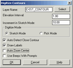
Function:
This command lets you digitize
contours as polylines one at a time. The first time it prompts you
the Digitize Contours
Dialog. Enter the layer name or select it from a list of
existing layer. Look at your plans and determine an elevation
interval that is between most of the contours and enter it in the
Elevation Interval field. You are able to modify both the value and
the direction of the elevation interval between digitizing contour
lines, using the buttons on the puck. If you decide to do Sketch
mode digitizing, you need to enter the increment field. To have
Takeoff automatically close contours whose beginning and ending
points are within a specified range, check the Auto Detect Close
Contour. Draw Labels would draw the elevation at the starting
point of the contour. In Pick mode, if you want the Takeoff to
automatically zoom the display to center around the last point when
you get near the edge of the screen while picking points, check the
Auto Zoom Center. Click OK to start digitizing.
Place your cursor at one end of the contour line and begin
digitizing the line. While digitizing a line, you can force a
contour to close on itself by pressing A on the puck to end the
contour and connect the last point to the first point, or remove a
mistake by pressing B on
the puck. At the end of the contour line, press Enter on your puck or keyboard.
The contour is completed, and the elevation for the next contour is
automatically incremented. You would be asked to digitize next
contour. If you press A on
the puck or enter Yes on
the keyboard, you can digitize another contour, or press B on the puck or enter No on the keyboard to finish
digitizing contours.
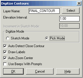
Digitize Contour
in Sketch Mode
Digitize Contour in Pick
Mode
Prompts:
Sketch Mode:
Digitize Contours Dialog
Enter Layer Name, Elevation
Interval, Increment in Sketch Mode if select Sketch Mode, and
toggle on/off Auto Detect Close Contour etc.
Increment(1.00)[A]/Direction(+)[B]/Elevation
<573.00>: 450 (enter elevation or press Enter to accept
current value)
Pick and drag to digitize (Enter to finish):
<Pen down> <Pen up> (press Enter on the puck or keyboard to
finish sketching)
1 polyline with 243 edges recorded.
Note:
If you are using puck layout 2,
Takeoff would prompt you differently here.
Pick and drag
to digitize (Press [0]/Enter to finish): <Pen
down> <Pen up> (press 0 on the puck or press Enter on the
keyboard to finish sketching)
1 polyline
with 243 edges recorded.
Close[A]/Undo[B]/Pick
to continue (Enter to finish): press Enter on the puck or keyboard to finish
the contour line
Digitize Another Contour [<Yes(A)>/No(B)]?
A (press A to digitize
next contour line)
Increment(1.00)[A]/Direction(+)[B]/Elevation
<451.00>: A
(Elevation is
automatically incremented. Press A on the puck or keyboard to
increase it by the Increment again.)
Increment(1.00)[A]/Direction(+)[B]/Elevation
<452.00>: press Enter on the puck or keyboard to start
digitizing
Pick and drag to digitize (Enter to finish): <Pen down>
<Pen up> (press
Enter on the puck or keyboard to finish sketching)
1 polyline with 234 edges
recorded.
Note:
If you are using puck layout 2, then
Takeoff would prompt you differently here.
Pick and drag
to digitize (Press [0]/Enter to finish): <Pen
down> <Pen up> (press 0 on the puck or press Enter on the
keyboard to finish sketching)
1 polyline
with 234 edges recorded.
Close[A]/Undo[B]/Pick
to continue (Enter to finish):
Digitize Another Contour [<Yes(A)>/No(B)]?
A (press A to digitize next contour
line)
Increment(1.00)[A]/Direction(+)[B]/Elevation
<453.00>: B
(Elevation is
automatically incremented. Press B on the puck or keyboard to
change the increment from positive to negative.)
Increment(1.00)[A]/Direction(-)[B]/Elevation
<452.00>: A (Press A on the puck or keyboard to increase
it by the Increment again.)
Increment(1.00)[A]/Direction(-)[B]/Elevation
<451.00>: A (Press A on the puck or keyboard to increase
it by the Increment again.)
Increment(1.00)[A]/Direction(-)[B]/Elevation
<450.00>: A (Press A on the puck or keyboard to increase
it by the Increment again.)
Increment(1.00)[A]/Direction(-)[B]/Elevation
<449.00>: A (Press A on the puck or keyboard to increase
it by the Increment again.)
Increment(1.00)[A]/Direction(-)[B]/Elevation
<448.00>: press Enter on the puck or keyboard to start
digitizing
Pick and drag to digitize (Enter to finish): <Pen down>
<Pen up> (press
Enter on the puck or keyboard to finish sketching)
1 polyline with 109 edges
recorded.
Note:
If you are using puck layout 2, then
Takeoff would prompt you differently here.
Pick and drag
to digitize (Press [0]/Enter to finish): <Pen
down> <Pen up> (press 0 on the puck or press Enter on the
keyboard to finish sketching)
1 polyline with 109 edges
recorded.
Close[A]/Undo[B]/Pick
to continue (Enter to finish): press Enter on the puck or keyboard to finish
the contour line
Digitize Another Contour [<Yes(A)>/No(B)]?
B (press B to finish
digitizing contour line in sketch mode)
Pick Mode:
Digitize Contours
Dialog
Enter Layer Name, Elevation Interval, Increment
in Sketch Mode if select Sketch Mode, and toggle on/off Auto Detect
Close Contour etc.
Increment(1.00)[A]/Direction(+)[B]/Elevation
<458.00>: press Enter on the puck or keyboard to start
digitizing
First point:
Close[A]/Undo[B]/Pick next point
(Enter to end): pick next point
(You can force
a contour to close on itself by pressing A or remove mistake by
pressing B.)
Close[A]/Undo[B]/Pick next point
(Enter to end): pick next point
Close[A]/Undo[B]/Pick next point
(Enter to end): pick next point
Close[A]/Undo[B]/Pick next point
(Enter to end): pick next point
Close[A]/Undo[B]/Pick next point
(Enter to end): press Enter to finish picking
Digitize Another Contour
[<Yes(A)>/No(B)]? A (press A to digitize next contour
line)
Increment(1.00)[A]/Direction(+)[B]/Elevation
<459.00>: press Enter on the puck or keyboard to start
digitizing
First point:
Close[A]/Undo[B]/Pick next point
(Enter to end): pick next point
Close[A]/Undo[B]/Pick next point
(Enter to end): pick next point
Close[A]/Undo[B]/Pick next point
(Enter to end): pick next point
Close[A]/Undo[B]/Pick next point
(Enter to end): pick next point
Close[A]/Undo[B]/Pick next point
(Enter to end): press Enter to finish picking
Digitize Another Contour
[<Yes(A)>/No(B)]? B (press B on the puck or enter No on the
keyboard to finish digitizing contour line in pick
mode)
Keyboard Command:
digcont_exist,
digcont_final
Pull-Down Menu Location:
Digitize
Prerequisite:
Have a digitizer board and a puck
connected to your computer, and have Wintab driver installed. The
digitizer has been correctly set up. Have done tablet calibration
for current drawing.
Sections
Functions:
This command allows you to digitize
section lines and store the section data in the section file you
have specified. The command first prompts you the Digitize Section Dialog. Enter the
section file name and determine if you want to digitize second and
third sections at the same station. Look at your plans and
determines the station interval, which is used to automatically
default to the next station value when digitizing a series of
stations. If the grids at all the stations have the same base
elevation, toggle on Use Fixed Base Grid Elevation. You can also
toggle on Interpolate Zero Offset Elevation, Prompt for Subgrades,
Prompt for Save for Each Section and Use Beeps with Prompts. Click
OK to start digitizing.
Takeoff prompts you to calibrate the section sheet before you
digitize the section lines. You pick three points and specify their
offsets to the centerline and elevations in order to determine the
horizontal and vertical intervals. Corners on the section grid are
preferred reference points. Place your cursor at one end of the
section line and begin digitizing the line. While digitizing a
line, you can remove a mistake by pressing A on the puck or entering Undo on the keyboard. At the
end of the section line, press
Enter on your puck or keyboard. The station is completed,
and the station value is automatically incremented. The command
would prompts to digitize next section. You can press A on the puck or enter Exit on the keyboard to finish
digitizing. If you want to continue to digitize next section,
press Enter or enter the
new station number. For every station after the first one, you can
calibrate the grid sheet by picking one reference point and specify
its offset and elevation. After you digitize the section lines on
your drawing, all the section data would be saved in a section file
(.sct).
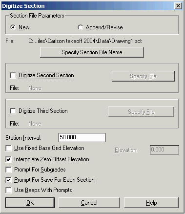
Prompts:
Digitize Section Dialog
Enter
Section File Name, Station Interval, and toggle on/off Use Fixed
Base Grid Elevation etc.
Section station to digitize
<0.000>: press Enter to start with station 0.0 or
enter a station number
Calibrate section
sheet
Pick First section sheet reference
point: pick a
grid point of this station on your drawing
Enter offset
<0.0>: press Enter to accept the offset or enter the
offset of the point to the centerline
Enter
elevation: 1030 (enter the Elevation of the reference
point)
Pick Second section reference
point: pick
the second grid point
Enter offset:
0 (enter the offset of the
point to the centerline)
Enter elevation:
1040 (enter the Elevation
of the reference point)
Pick Third section reference
point: pick
the third grid point
Enter offset:
50 (enter the offset of
the point to the centerline)
Enter elevation:
1040 (enter the Elevation
of the reference point)
3 calibration points
Transformation
type:
Orthogonal
Affine Projective
------------------------------------------------------------------------------
Outcome of
fit:
Success
Exact Impossible
RMS
Error:
11.49
Standard
deviation:
2.38
Largest
residual:
14.08
At
point:
2
Second-largest
residual:
14.08
At
point:
1
Digitize break point for DRAWING1
section 0.000 (Enter to end): pick a point on the section line
Offset: -39.81 Elev: 1028.80
Digitize break point for DRAWING1
section 0.000 (Undo[A],Enter to end):
pick a point on the section
line
Offset: -9.94 Elev: 1030.03
Digitize break point for DRAWING1
section 0.000 (Undo[A],Enter to end):
pick a point on the section
line
Offset: 49.44 Elev: 1034.93
Digitize break point for DRAWING1
section 0.000 (Undo[A],Enter to end):
press Enter to finish
Save changes to DRAWING1 section
0.000 [<Yes(A)>/No(B)]? A (press A or B)
Exit[A]/Section station to
digitize <50.000>: 200 (enter next station number)
Calibrate next
section
Pick section reference
point: pick a
grid point of the station on your drawing
Enter offset
<0.00>: press Enter to accept the offset or enter the
offset of the point to the centerline
Enter elevation
<1030.00>: 1020 (enter the Elevation of the reference
point)
Digitize break point for DRAWING1
section 200.000 (Enter to end): pick a point on the section line
Offset: -40.40 Elev: 1008.07
Digitize break point for DRAWING1
section 200.000 (Undo[A],Enter to end):
pick a point on the section
line
Offset: -5.38 Elev: 1019.98
Digitize break point for DRAWING1
section 200.000 (Undo[A],Enter to end):
pick a point on the section
line
Offset: 27.86 Elev: 1030.02
Digitize break point for DRAWING1
section 200.000 (Undo[A],Enter to end):
pick a point on the section
line
Offset: 50.33 Elev: 1035.80
Digitize break point for DRAWING1
section 200.000 (Undo[A],Enter to end):
press Enter to finish
Save changes to DRAWING1 section
200.000 [<Yes(A)>/No(B)]? A (press A or B)
Exit[A]/Section station to
digitize <250.000>: A (press A to finish or enter the station
number to continue)
Keyboard Command:
digxsec
Pull-Down Menu Location:
Digitize
Prerequisite:
Have a digitizer board and a puck
connected to your computer, and have Wintab driver installed. The
digitizer has been correctly set up. Have done tablet calibration
for current drawing.
End Areas
Functions:
There are two types of end areas:
cut area and fill area. This command allows you to digitize both
cut area and fill area on the drawing and writes data to a .ew
file. The command first prompts you to calibrate the section sheet
by picking three points and specify their offsets to the centerline
and elevations in order to determine the horizontal and vertical
intervals .Corners on the section grid are preferred reference
points. Then it prompts you to digitize the cut area and fill area
respectively. Place your cursor at one end of the end area and
begin digitizing the outline of the area. At the end of the section
line, press Enter on your
puck or keyboard. The end area is completed, and its area is
printed on the command line, and you are prompted to digitize next
end area. After you finish all the end area at one station,
accumulated cut area and fill area are computed and printed out on
the screen. All data of cut area and fill area at every station
would be saved in the area file (.ew) that you have
specified.
Prompts:
Calibrate section sheet
Pick First section sheet reference
point: pick a
point on the drawing
Enter offset
<0.0>: press Enter to accept the offset (or enter
the offset of the point to the centerline)
Enter elevation:
1020 (enter the Elevation
of the reference point)
Pick Second section reference
point: pick a
point
Enter offset:
0 (enter the offset of the
point to the centerline)
Enter elevation:
1030 (enter the Elevation
of the reference point)
Pick Third section reference
point: pick a
point
Enter offset:
50 (enter the offset of
the point to the centerline)
Enter elevation:
1030 (enter the Elevation
of the reference point)
3 calibration points
Transformation
type:
Orthogonal
Affine Projective
------------------------------------------------------------------------------
Outcome of
fit:
Success
Exact Impossible
RMS
Error:
11.69
Standard
deviation:
2.40
Largest
residual:
14.29
At
point:
2
Second-largest
residual: 14.29
At
point:
3
Digitize cut area (Enter to
end): pick a point that is on the outline of the
cut area, 0*(0.211129 1030.76)
Digitize cut area (Enter to
end): pick a point that is on the outline of the
cut area, 1*(11.5804 1030.49)
Digitize cut area (Enter to
end): pick a point that is on the outline of the
cut area, 2*(17.8643 1030.73)
Digitize cut area (Enter to
end): pick a point that is on the outline of the
cut area, 3*(19.0216 1032.35)
Digitize cut area (Enter to
end): pick a point that is on the outline of the
cut area, 4*(-0.777246 1030.75)
Digitize cut area (Enter to
end): press
Enter to finish
End area: 17.2312
Accumulated Cut Area: 17.2312
More Cut Areas
[Yes(A)/<No>(B)]? press A to digitize more Cut Areas, or press
B to finish digitizing Cut Areas.
Accumulated Cut Area: 17.2312
Digitize fill area (Enter to
end): pick a point that is on the outline of the
fill area, 0*(-18.9614 1029.65)
Digitize fill area (Enter to
end): pick a point that is on the outline of the
fill area, 1*(-18.1315 1030.75)
Digitize fill area (Enter to
end): pick a point that is on the outline of the
fill area, 2*(-11.9592 1030.49)
Digitize fill area (Enter to
end): pick a point that is on the outline of the
fill area, 3*(-2.06761 1030.72)
Digitize fill area (Enter to
end): pick a point that is on the outline of the
fill area, 4*(-10.0082 1030.01)
Digitize fill area (Enter to
end): pick a point that is on the outline of the
fill area, 5*(-18.531 1029.67)
Digitize fill area (Enter to
end): press
enter to finish
End area: 8.64646
Accumulated Cut Area: 8.64646
More Fill Areas
[Yes(A)/<No>(B)]? press A to digitize more Fill Areas, or press
B to finish digitizing Fill Areas.
Accumulated Cut Area: 8.64646
Total Cut Area: 17.2312
Total Fill Area: 8.64646
Store data to file
[<Yes>(A)/No(B)]? press A or B
Opened file: C:\Program Files\Carlson TakeOff
2004\DATA\Drawing1.ew
Station Number:
1 (enter Station
Number)
Data Stored in file: C:\Program Files\Carlson TakeOff
2004\DATA\Drawing1.ew
Digitize another station
[<Yes>(A)/No(B)]? B (press A or B)
Keyboard Command:
digendar
Pull-Down Menu Location:
Digitize
Prerequisite:
Have a digitizer board and a puck
connected to your computer, and have Wintab driver installed. The
digitizer has been correctly set up. Have done tablet calibration
for current drawing.