Digitize Sections
This command allows you to digitize section lines and store the
section data in the section file you have specified. The command
first prompts you the Digitize
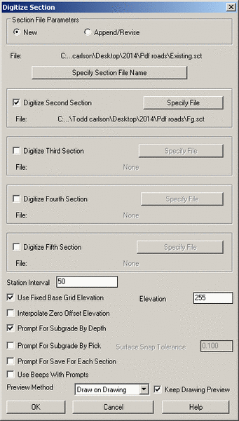
Section Dialog. Enter the section file name and determine if
you want to digitize second and third sections at the same station
(i.e., for existing, finish grade, unsuitable, etc.). Look at your
plans and determines the station interval, which is used to
automatically default to the next station value when digitizing a
series of stations. If the grids at all the stations have the same
base elevation, toggle on Use Fixed Base Grid Elevation. The
Interpolate Zero Offset Elevation option calculates a
section point at the zero offset when the zero offset point isn't
digitized. The Prompt for Save for Each Section option can
be used to save the SCT file after completing each station. The
Use Beeps with Prompts option gives audio feedback to help
keep your eyes on the sheet. Surface Snap Tolerance sets the
maximum distance that the program will automatically snap the tie
back point between the subgrade and design surface. The Prompt
For Descriptions option will prompt for a description for each
digitized section point.
There are two ways to account for Subgrades. Prompt For Subgrade
By Depth will ask you for a subgrade depth while you are
digitizing a section file and apply that subgrade depth below each
point you pick for that section. If no subgrade linework is shown
on the plans, but the depth is known, this is a good option.
Prompt For Subgrade By Pick allows you to digitize in the
subgrade linework after initial section has been digitized. This
option is best when your Subgrade Depth is not uniform.
Preview Method offers 2 ways to view the sections as you
digitize. "Graphic Dialog" displays the section data in a
grid dialog and is best when digitizing from paper plans. "Draw
on Drawing" draws 2D polylines in your CAD drawing and is best
when digitizing over an Image in your drawing. "Keep Drawing
Preview" will leave the 2D polylines in your CAD drawing (having
this checked off will erase the 2D polylines after each station).
Click OK to start digitizing.
Takeoff prompts you to calibrate the section sheet before you
digitize the section lines. You pick three points and specify their
offsets to the centerline and elevations in order to determine the
horizontal and vertical intervals. Corners on the section grid are
preferred reference points. Place your cursor at one end of the
section line and begin digitizing the line. While digitizing a
line, you can remove a mistake by pressing A on the puck or entering Undo on the keyboard. At the
end of the section line, press
Enter on your puck or keyboard. The station is completed,
and the station value is automatically incremented. The command
would prompts to digitize next section. You can press A on the puck or enter Exit on the keyboard to finish
digitizing. If you want to continue to digitize next section,
press Enter or enter the
new station number. For every station after the first one, you can
calibrate the grid sheet by picking one reference point and specify
its offset and elevation. After you digitize the section lines on
your drawing, all the section data would be saved in a section file
(.sct).
Prompts
Digitize Section Dialog
Enter Section File Name, Station Interval, and toggle on/off Use
Fixed Base Grid Elevation etc.
Section station to digitize
<0.000>: press Enter to start with station 0.0 or
enter a station number
Calibrate section
sheet
Pick First section sheet reference
point: pick a
grid point of this station on your drawing
Enter offset
<0.0>: press Enter to accept the offset or enter the
offset of the point to the centerline
Enter
elevation: 1030 (enter the Elevation of the reference
point)
Pick Second section reference
point: pick
the second grid point
Enter offset:
0 (enter the offset of the
point to the centerline)
Enter elevation:
1040 (enter the Elevation
of the reference point)
Pick Third section reference
point: pick
the third grid point
Enter offset:
50 (enter the offset of
the point to the centerline)
Enter elevation:
1040 (enter the Elevation
of the reference point)
3 calibration points
Transformation
type:
Orthogonal
Affine Projective
------------------------------------------------------------------------------
Outcome of
fit:
Success
Exact Impossible
RMS
Error:
11.49
Standard
deviation:
2.38
Largest
residual:
14.08
At
point:
2
Second-largest
residual:
14.08
At
point:
1
Digitize break point for DRAWING1
section 0.000 (Enter to end): pick a point on the section line
Offset: -39.81 Elev: 1028.80
Digitize break point for DRAWING1
section 0.000 (Undo[A],Enter to end):
pick a point on the section
line
Offset: -9.94 Elev: 1030.03
Digitize break point for DRAWING1
section 0.000 (Undo[A],Enter to end):
pick a point on the section
line
Offset: 49.44 Elev: 1034.93
Digitize break point for DRAWING1
section 0.000 (Undo[A],Enter to end):
press Enter to finish
Save changes to DRAWING1 section
0.000 [<Yes(A)>/No(B)]? A (press A or B)
Exit[A]/Section station to
digitize <50.000>: 200 (enter next station number)
Calibrate next
section
Pick section reference
point: pick a
grid point of the station on your drawing
Enter offset
<0.00>: press Enter to accept the offset or enter the
offset of the point to the centerline
Enter elevation
<1030.00>: 1020 (enter the Elevation of the reference
point)
Digitize break point for DRAWING1
section 200.000 (Enter to end): pick a point on the section line
Offset: -40.40 Elev: 1008.07
Digitize break point for DRAWING1
section 200.000 (Undo[A],Enter to end):
pick a point on the section
line
Offset: -5.38 Elev: 1019.98
Digitize break point for DRAWING1
section 200.000 (Undo[A],Enter to end):
pick a point on the section
line
Offset: 27.86 Elev: 1030.02
Digitize break point for DRAWING1
section 200.000 (Undo[A],Enter to end):
pick a point on the section
line
Offset: 50.33 Elev: 1035.80
Digitize break point for DRAWING1
section 200.000 (Undo[A],Enter to end):
press Enter to finish
Save changes to DRAWING1 section
200.000 [<Yes(A)>/No(B)]? A (press A or B)
Exit[A]/Section station to
digitize <250.000>: A (press A to finish or enter the station
number to continue)
Keyboard Command:
digxsec
Prerequisite: For
"on-screen" digitizing, have an image loaded and Digitizer Settings
set to "Use Mouse". For paper plan digitizing, have a digitizer
board and a puck connected to your computer, and have Wintab driver
installed. The digitizer has been correctly set up. Have done
tablet calibration for current drawing.