Profiles
This command allows you to digitize profile lines and store the
profile data into the profile file (.pro) you have specified. The
command first prompts you the Digitize Profile Dialog. Enter the
profile file name and determine if you want to digitize up to five
profiles from the same grid. Next, determine the Profile
Type: Ground, Road, or Pipe. Selecting Road will prompt you for
a "Vertical Curve" to be applied between the current point and
previous profile point. If no Vertical Curve exists, type "0";
entering without specifying any Vertical Curve will turn off the VC
prompt on subsequent profile points. Selecting Pipe will prompt you
for a "Step up for the pipe" and "Enter the Pipe size" at each
profile point. With Ground, there are no additional prompts.
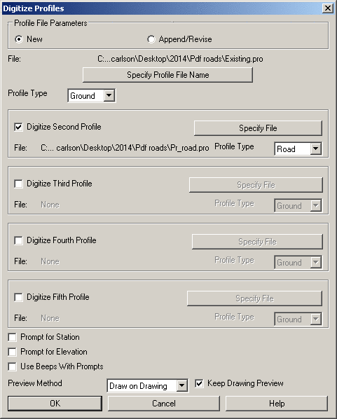
Towards the bottom half of the dialog, there are toggles for
Prompt for Station and Prompt for Elevation. These
will show you a preview value for the Station and Elevation based
on the point that you picked. Press Enter to except or type in a
new value in manually. This is most useful for accurate import of
Road and Pipe data. Also at the bottom, Preview Method offers 2 ways to view
the profiles as you digitize. "Graphic Dialog" displays the profile
data in a grid dialog and is best when digitizing from paper plans.
"Draw on Drawing" draws 2D polylines in your CAD drawing and is
best when digitizing over an Image in your drawing. "Keep Drawing
Preview" will leave the 2D polylines in your CAD drawing (having
this checked off will erase the 2D polylines after each
station).
After clicking OK in the main dialog, Takeoff prompts you to
calibrate the profile sheet before you digitize the profile
lines. You will pick three points and specify their station and
elevations in order to determine the horizontal and vertical
scales. Corners on the profile grid are preferred reference points.
Once calibrated, place your cursor at one end of the profile line
and begin digitizing the line. While digitizing a line, you can
remove a mistake by pressing
A on the puck or entering
Undo on the keyboard. At the end of the profile line,
press Enter on your puck or
keyboard. The command then prompts you to digitize the next
profile. You can press A on
the puck or enter Exit on
the keyboard to finish digitizing. After you digitize the profile
lines on your drawing, all the profile data would be saved in a
profile file (.pro).
Prompts
Calibrate profile
sheet
Pick First profile sheet reference
point: pick a
grid point of a station on your drawing
Enter station <0.0>:
1000 press Enter to
accept the station or enter a new station value
Enter elevation:
95 (enter the Elevation of the reference
point)
Pick Second profile reference
point: pick a
second grid point
Enter station: 1200
(enter the grid's
station)
Enter elevation:
110 (enter the Elevation
of the reference point)
Pick Third profile reference
point: pick a
third grid point
Enter station:
1500 (enter the grid's
station)
Enter elevation:
105 (enter the Elevation
of the reference point)
3 calibration points
Transformation
type:
Orthogonal
Affine Projective
------------------------------------------------------------------------------
Outcome of
fit:
Success
Exact Impossible
RMS
Error:
11.49
Standard
deviation:
2.38
Largest
residual:
14.08
At
point:
2
Second-largest
residual:
14.08
At
point:
1
Digitize break point/ (Enter to
end): pick a
point on the profile line
Station: 1000 Elev: 106.77
Digitize break point
(Undo[A],Enter to end): pick a point on the profile line
Station: 1145 Elev: 101.18
Digitize break point
(Undo[A],Enter to end): pick a point on the profile line
Station: 1440 Elev: 100.49
Digitize break point
(Undo[A],Enter to end): press Enter to finish
Keyboard Command:
digprof
Prerequisite: For
"on-screen" digitizing, have an image loaded and Digitizer Settings
set to "Use Mouse". For paper plans, have a digitizer board and a
puck connected to your computer, and have Wintab driver installed.
The digitizer has been correctly set up. Have done tablet
calibration for current drawing.