SurvNET is capable of processing either C&G (.CGR) raw data files, Carlson (.RW5) raw data files or SDMS (.PRJ) raw data files. If the raw data is in another format, you can use our conversion tools to create one of the supported formats. Select the desired type of raw file editor as described under Settings -- Global Settings.
Measurement, coordinate, elevation and direction (Brg/Az)
records are all recognized. Scale factor records in the .CGR file
are not processed since SurvNET calculates the State Plane scale
factors automatically.
Once raw data is entered, the network can be processed. Often it
is desired to apply a standard error for a particular measurement
or control point that is different than those set in the
Project Settings. This can be accomplished by editing the
Standard
Errors of specific or groups of points or
measurements.
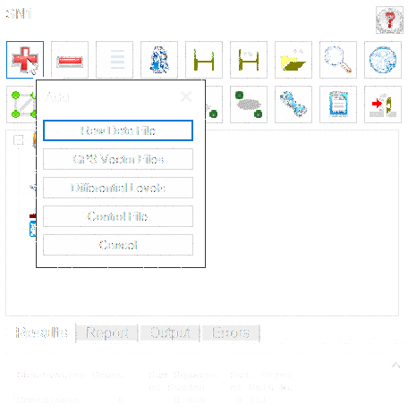
There are four types of Raw Data Files files you can add and
process as part of a single network:
Raw Data File -
traditional total station files (usually ground measurements)
GPS Vector File - GPS
observations in the form of vector data
Differential Levels -
standard differential level or Trig observations for vertical
control
Control File -
point records to be used as control for the network.
To process traverse raw data, click the Add (red +
button) and select the Raw Data File to insert raw total
station files into the list. Use Remove (red -
button) to remove raw files from the list. All the files in this
list are included in the Least Squares adjustments. Having the
ability to choose multiple files allows one to keep Control in one
file and measurements in another file. Or, different files
collected at different times can be processed all at one time. If
you have multiple crews working on the same project using different
equipment, you can have "crew-specific" raw data files with
standard error settings for their particular equipment. Having
separate data files is also a convenient method of working with
large projects. It is often easier to debug and process individual
raw files. Once the individual files are processing correctly, all
the files can be included for a final adjustment. You can either
enter C&G (.CGR) raw files or Carlson (.RW5) files into the
list for processing. You cannot have both .CGR and .RW5 files in
the same project to be processed at the same time. Notice that you
have the ability to highlight multiple files when removing files
from the project.
Note that if you are processing Carlson RW5 total station files,
you have the option of including GPS vectors that can be collected
by SurvCE/SurvPC and stored in the RW5 file. Alternatively, you can
select the RW5 file in the GPS vector section. If the
"Include any GPS vectors" option in the Total Station Data Files
section is checked, you will have the option to use the Base Point
records in the RW5 file as control. If "Use BP records as
control" is NOT checked, or the RW5 file is selected in the GPS
vector section, you must define the control in either the RW5 file
as POINT records or in a Supplemental Control File.
To set these options, select the Settings
option from the main menu.
GPS vector files can be entered and processed. Both GPS vector files and total station raw files can be combined and processed together. You must have chosen the 3D mathematical model in the Coordinate System tab in order to include GPS vectors in the adjustment.
A variety of popular GPS vector file formats are supported, including (but not necessarily limited to):
The following is a typical vector record in the StarNet ASCII format. GPS vectors typically consist of the 'from' and 'to' point number, the delta X, delta Y, delta Z values from the 'from' and 'to' point, with the XYZ deltas being in the geocentric coordinate system. Additionally the variance/covariance values of the delta XYZ's are included in the vector file.
.GPS WEIGHT COVARIANCE
C PRS34452 1305780.345005 -4667085.299019 4132689.544939 0.005000 0.005000 0.005000 --MON
C UCNJ 1305780.345005 -4667085.299019 4132689.544939 0.00000100 0.00000100 0.00000100 --MON
G1  UCNJ-1000    8399.71318061   -4742.15645068   -8036.07224424 --MNS
G2   3.939428e-006  2.474560e-005  1.160301e-005
G3   3.924536e-006 -3.360765e-006 -1.028503e-006
G1  UCNJ-1001    8328.15569476   -4796.59445569   -8072.25948922 --MNS
G2   9.596618e-007  1.687749e-005  1.936038e-006
G3   1.176891e-007 -8.668020e-009 -4.798408e-006
The first line defines what values are in the G2 and G3 records. It can be either GPS WEIGHT COVARIANCE (G2 is Variance, G3 is Covariance), or GPS WEIGHT STDERRCORRELATION (G2 is standard error, G3 is standard error correlation). This line is optional; the default is COVARIANCE.
The next two lines are coordinate control records. These records are also optional. If used, they must be Geocentric Coordinates (XYZ) in metric units. The format is as follows:
C PointName X Y Z StdErrX StdErrY StdErrZ --PointDescription
The standard errors and point description are optional.
The GO record is a comment.
The G1 record includes the 'from' and 'to' points and the delta X, delta Y, and delta Z in the geocentric coordinate system and an optional description of the rover point.
The G2 record is the variance (or standard error) of X,Y, and Z. The G3 record contains the covariance (or standard error correlation) of XY, ZX, and ZY. Most all GPS vector files contain the same data fields in different formats.
Use the 'Add' button to insert GPS vector files into the list. Use the 'Remove' button to remove GPS vector files from the list. All the files in this list will be used in the least squares adjustments. All the GPS files in the list must be in the same format. If the GPS file format is ASCII you have the option to edit the GPS vector files. The Edit option allows the editing of any of the ASCII GPS files using Notepad. Typically, only point numbers or point descriptions would be edited. The variance/covariance values are used to determine the weights that the GPS vectors will receive during the adjustment and are not typically edited.
Differential and Trig level files can be entered and processed. Differential or Trig Level raw files have a .TLV extension and are created using the Carlson Level Editor. The Carlson Level Editor has several Import options that allow you to bring in levels from different formats (e.g. Leica, Trimble, Topcon, etc). You can process level data in the same project with the traverse and GPS vector data but the vertical measurements in the traverse/vectors will be part of the adjustment. If you want to use the elevations calculated ONLY from the level data, you must process it in a separate project after your traverse/vector data has been adjusted. The elevations will be written to the Output Coordinate file. Make sure your point numbers in the level data match the points in the traverse/vector data.
Supplemental Control File: The supplemental control file option allows the user to designate an additional coordinate file to be used as Control. The supplemental control file can be from a variety of different file types, including (but not necessarily limited to):
Note: For additional information on file format pertaining to the file formats above, refer to the Supplemental Control Files section of the documentation.
Note: You will not be allowed to use the same file for supplemental control points and for final output. Least Squares considers all points to be measurements. If the output file is also used as a supplemental control file, then after the project has been processed all the points in the project would now be in the control file and all the points in the file would now be considered control points if the project was processed again. The simplest and most straight-forward method to define control for a project is to include the control coordinates in a raw data file.
In order to process a raw data file, you must have (as a minimum) a control point and a control azimuth, or two control points. Control points can be inserted into the raw data file or alternately control points can be read from a coordinate file as linked via the Input Files portion of the program.
The major advantage of putting coordinate control points in the actual raw data file is that specific standard errors can be assigned to each control point (as described in the Control Standard Errors section above). If you do not include an SE record, the standard error will be assigned from the NORTH, EAST, and ELEVATION standard errors from the Control Standard Error project default values dialog box.
The standard errors for the control points from a supplemental control file will be assigned the NORTH and EAST standard errors from the project settings dialog box.
In the ASCII .NEZ file, the coordinate records need to be in the following format:
Pt. No., Northing, Easting, Elevation,
Description<cr><lf>
103, 123233.23491, 238477.28654, 923.456, Mon
56-7B<CR><LF>
Each line is terminated with the "non-printing" carriage-return <CR> and line-feed <LF> characters. When viewed in a simple ASCII file editor such as Windows Notepad, the file snippet above would resemble:
Pt. No., Northing, Easting, Elevation, Description
103, 123233.23491, 238477.28654, 923.456, Mon 56-7B
In the ASCII latitude and longitude file, the records need to be in the following format:
Pt. No., Latitude (NDDD.mmssssss), Longitude (WDDD.mmssssss),
Elevation (Orthometric), Description<cr><lf>
FRKN,N35.113068642,W083.234174724,649.27<CR><LF>
Each line is terminated with the "non-printing" carriage-return <CR> and line-feed <LF> characters. When viewed in a simple ASCII file editor such as Windows Notepad, the file snippet above would resemble:
Pt. No., Latitude (NDDD.mmssssss), Longitude (WDDD.mmssssss),
Elevation (Orthometric), Description
FRKN,N35.113068642,W083.234174724,649.27
In the ASCII XYZ Geocentric file, the records need to be in the following format:
Pt. No. X Y Z Descriptions<cr><lf>
105 1413426.6020 -4537671.2000 4239299.9360
MON<CR><LF>
Each line is terminated with the "non-printing" carriage-return <CR> and line-feed <LF> characters. When viewed in a simple ASCII file editor such as Windows Notepad, the file snippet above would resemble:
Pt. No. X Y Z Descriptions
105 1413426.6020 -4537671.2000 4239299.9360 MON
NOTE: It is not allowed for the supplemental control file and the final output file to be the same file. Since Least Squares considers all points to be control points, only control points should be in a supplemental control file.
Once raw data files are added to the network it can be adjusted
using the parameters as set in the Project Settings. In many
instances, there will be a need to assign specific standard errors
for particular measurements or control points. This can be
accomplished by editing individual points or measurements or by
assigning a standard error to a particular raw data file.
Standard errors are estimated errors that are assigned to measurements or coordinates. A standard error is an estimate of the standard deviation of a sample. A higher standard error indicates a less accurate measurement. The higher the standard error of a measurement, the less weight it will have in the adjustment process.
Although you can set default standard errors for the various types of measurements in the Project Settings of SurvNET, standard errors can also be placed directly into the raw data file. A standard error record inserted into a raw data file applies to all the measurements following the SE record. The standard error does not change until another SE record is inserted that either changes the specific standard error, or sets the standard errors back to the project defaults. The advantage of entering standard errors into the raw file is that you can have different standard errors for the same type measurement in the same job.
For example, if you used a 1" total station with fixed backsights and foresights for a portion of a traverse and a 10" total station with backsights and foresights to hand-held prisms on the other portion of the traverse, you would want to assign different standard errors to reflect the different methods used to collect the data.
Make sure the SE record is placed before the measurements for which it applies. If you do not have standard errors defined in the raw data file, the default standard errors in the project settings will be applied to the entire file.
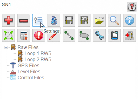
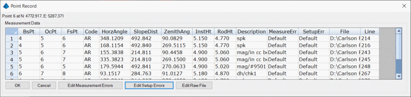
The dialog box option allows users to edit raw field data
directly through a the typical Carlson data Editor by selecting a
raw file and right-clicking:

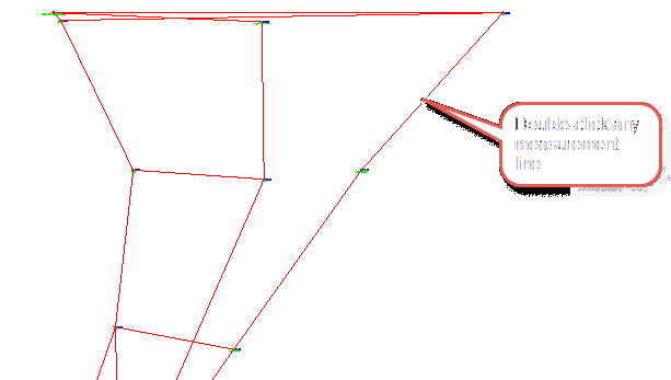
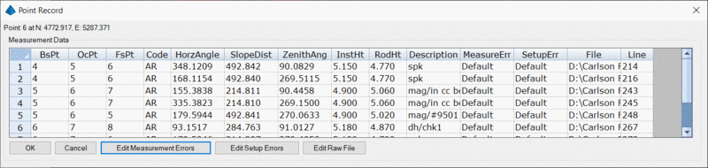
With the dialog box editor, users can review and edit
information for points, vectors and measurement lines by selecting
the information button ![]() or by double-clicking any
entity.
or by double-clicking any
entity.
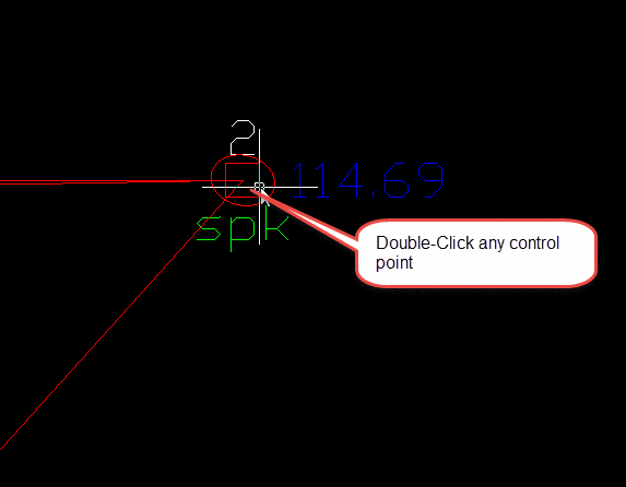
Select any a graphic entity such as a traverse line or control point and double-click on it.

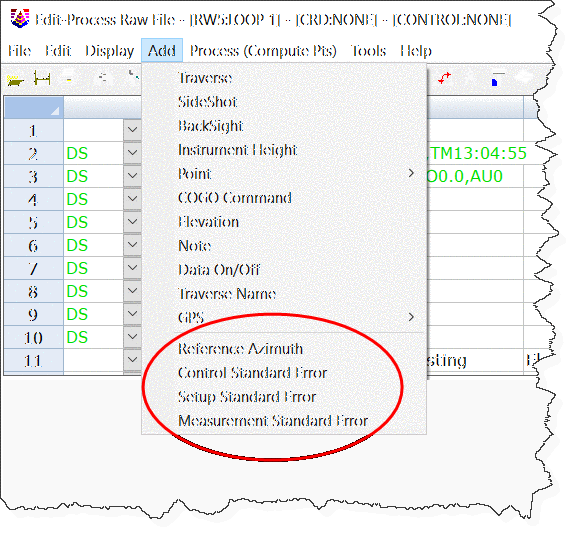
You can insert or add Control Standard Error records for a
specific point by double-clicking on a control point and selecting
Control Standard Error

You can set standard errors for Northing, Easting, Elevation, and
Azimuth selecting the Edit Control Errors option.
Azimuth standard errors are entered in seconds. The North, East and
Elevation standard errors affect the PT (coordinate) and EL
(elevation) records.
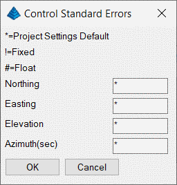
You can hold the North, East and Elevation fixed by entering an
exclamation "!" symbol. You can allow the North, East and Elevation
to FLOAT by entering a hash (or "pound") "#" symbol. You can also
assign the North, East and Elevation actual values. If you use an
asterix "*" symbol, the current standard error value will return to
the control standard error project defaults.
North     East    Elevation    Azim
!          !         !                (Fix all values)
#          #         #         30.0   (Allow the N., E. & Elevation to Float)
0.01      0.01      0.03        5.0   (assign values)
*          *         *            *   (return the control standard errors back to project defaults)
When you fix a coordinate point, the original value does not change during the adjustment and all measurements will be adjusted to fit the fixed point. If you allow a value to float, it will not be used in the actual adjustment, it will just be used to help calculate the initial coordinate values required for the adjustment process. Placing a very high or low standard error on a coordinate point accomplishes almost the same thing as setting the standard error as float or fixed. The primary purpose of using a float point is if SurvNET cannot compute preliminary values, a preliminary float value can be computed and entered for the point.
Direction records cannot be FIXED or FLOAT. You can assign a low standard error (or zero to fix) if you want to weight it heavily, or a high standard error to allow it to float.
In the example below, the first CSE record containing the '!' character and sets points 103, 204, and 306 to be fixed. The last CSE record contains the '*' character. It sets the standard errors for point 478 and any other points that follow to the project settings. The Azimuth standard error was left blank.
You can set the standard errors for various types of
measurements for a specific measurement by double-clicking
on a drawing entity (line or point) and selecting Edit
Measurement Errors
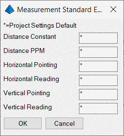
     Distance    Point       Read      V.Point     V.Read     PPM
MSE     0.01       3           3          3           3        5
You can enter any combination of the above values. If you do not want to change the standard error for a particular measurement type, leave it blank.
If you use an "*" symbol, the standard error for that measurement type will return to the standard measurement error project defaults.
These standard errors are a measure of how accurately the
instrument and target can be set up over the points as discussed in
the Instrument and Target Standard Errors section. You can edit a
particular setup by double-clicking on that point or measurement
line and selecting Edit Setup Errors
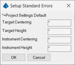
       Rod Ctr         Inst Ctr        Inst Ht          Rod Hgt
SSE     0.005           0.005           0.01            0.01
You can enter any combination of the above values. If you do not want to change the standard error for a particular measurement type, leave it blank.
If you use an "*" symbol, it will return the standard error to the Instrument and Target Standard Errors project default values.
One of the benefits of SurvNET is the ability to process redundant measurements. In terms of total station data, redundant measurement is defined as measuring angles and/or distances to the same point from two or more different setups.
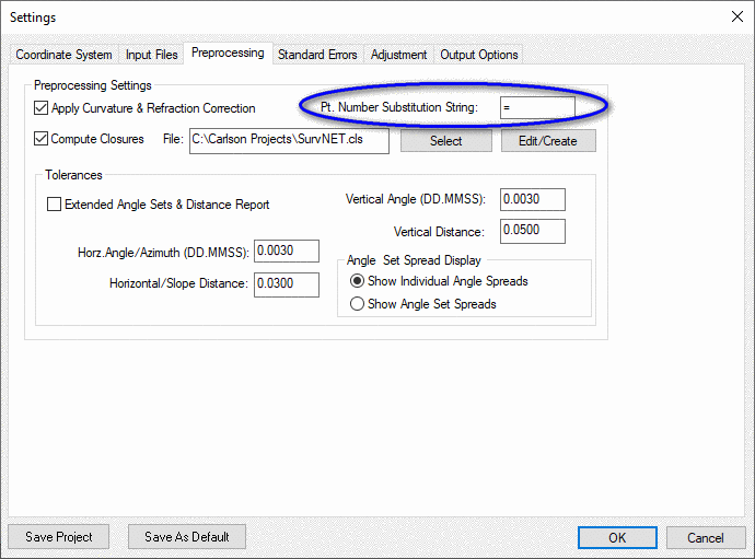
It is required that the same point number be used when locating a point that was previously recorded. However, since some data collectors will not allow you to use the same point number if the point already exists, SurvNET also uses the following convention for collecting redundant points while collecting the data in the field:
If the point description contains a user-defined string, for example an "=" (equal sign) followed by the original point number, SurvNET will treat that measurement as a redundant measurement to the point defined in the description field. The user-defined character or string is set in the Project Settings dialog. For example, if point number 56 has the description "=12", we will treat it as a measurement to point 12 and point 56 will not exist. Make sure the Preprocessing Settings dialog box has the Pt. Number Substitution String set to the appropriate value.
Alternately, the point numbers can be edited after the raw data has been downloaded from the data collector.