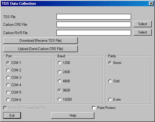
This command does two main functions for a variety of popular data collectors. First, this command transfers (uploads and downloads) data between the data collector and Carlson. Second, this command converts data formats between the data collector format and the Carlson format. So, if you already have the data file on the computer, you can skip the transfer function and just perform the conversion function.
The transfer function does the conversion at the same time. In
most cases, the download from the data collector produces a raw
(.RW5) file (field notes) and/or a coordinate (.CRD) file
(coordinate points). Several of the download programs have an
option to automatically run the Edit-Process Raw Data File
command after downloading raw data. You can also send, or upload, a
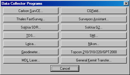
coordinate (.CRD) file. The dialog shown here appears when the menu
command is selected.
Carlson SurvCE: For Carlson Software data collection
programs SurvCE and SurvStar. This button produces the SurvCOM
dialog and program.
Prepare Geoid for SurvCE: Creates a subset of a geoid as a
.GSF file to load into SurvCE.
CG Field: For CG Field programs.
Magellan/Thales FastSurvey: For Magellan and Thales
FastSurvey data collectors.
Surveyors Assistant: For data collectors running Surveyors
Assistant software (Corvallis MC2, MC5 and Pentax SC5).
Sokkia SDR: For SDR2 through SDR 33 and other collectors
that have a SDR format like the Trimble.
Sokkia G2: Specifically for the SDR2.
TDS: For data collectors that use TDS software (Ranger,
HP48, HP95, Husky FS-2 & FS-3, Corvallis MC-V and TOPCON FS2,
FC95 and FC48).
SMI: For SMI data collectors on the HP48.
Leica: For Leica GIF-10 module, GeoCOM for older Leica and
DBX for newer Leica instruments.
Nikon: For Nikon DTM and DR-48 total stations.
Geodimeter: For the Geodimeter Geodat collector.
Topcon 210/310/220/GPT2000: Supports these Topcon
models.
MDL Laser: For MDL Laser instruments.
General Kermit Transfer: For general transferring using
Kermit.
Note: In the following text, the term SurvCE will apply to SurvCE, SurvStar, and Sokkia G2
Connect the serial cable. Select Data Transfer from the on the handheld. Choose Carlson/Carlson Survey Download. This leads to a File Transfer screen on SurvCE, which says "Awaiting Connection". All the action is on the PC side. There is no time delay in this handshake. It will wait for the PC program to catch up. When you connect the cable from SurvCE to the PC, Microsoft ActiveSync may interfere and say "Connect to PC?" If you get this question, say No or otherwise terminate the Microsoft ActiveSync linkage. Start the Carlson portion of this link by choosing Survey, Data Collectors, then the SurvCE option. If connection is automatically established, SurvCE will display, "Connected to PC".
If only the left side of the screen displays data, then you do not yet have a connection. Press the Connect button located at the bottom left of the file transfer dialog. The transfer program will respond with Retrieving File List. Once the file list has been retrieved, the left side of the dialog box will show files located in the specified path on the PC and the right side of the dialog displays the files located in the designated path on the remote. You can change directories by scrolling to the top of the file list and choosing Up One Level (just like in Windows).
To transfer one or more files, simply select or highlight the desired files and select the transfer button. More than one file can be transferred from the remote to the PC or from the PC to the remote during the transfer process. Standard Windows selection options apply. For example, selecting one file and then while pressing the shift key on the PC, selecting another file deeper on the list will select all the files in between the first and last selected. You can also select the first file to transfer and press and hold down the shift key and use the down arrow to specify the range of files to transfer. Pressing and holding the control key on the keyboard allows for the selection of multiple files in any selection order, by picking the files with the left mouse button.
After the files have been selected, press the transfer button. When the transfer is complete, the program will return a "Transfer Complete" message, and will then proceed to update the file lists on the PC and the Remote.
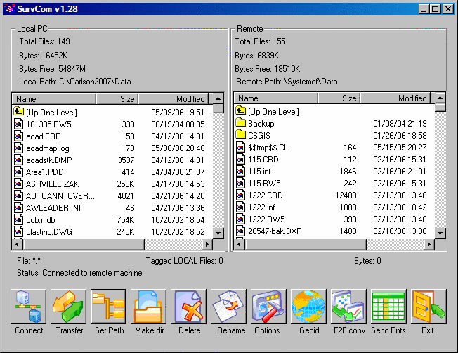
The following information describes the buttons on the bottom row of the SurvCOM dialog box. The button name is on the left in bold:
Connect: After selecting Data Transfer in SurvCE, press
this button to start the connection. Once connection is made, the
status line on the
file transfer utility dialog box will show Connected to the remote
machine.
Transfer: Pressing this button transfers selected files from either the Remote to the PC, or the PC to the Remote.
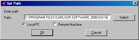
Set Path: This option allows for the specification of the
desired source and destination drives and folders for both the PC
and the Remote device. For example, if you were downloading, or
copying files from the Remote device to the PC, to specify a source
path on the remote device, select the Remote Machine toggle and
then type in the desired path in the path field. To specify a
destination path on the PC, select the Local PC toggle and type in
the desired path the path field. When a change to either path is
made, the transfer utility will retrieve a new file list from the
specified paths.
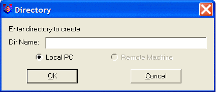
Make dir: This option allows for creation of directories
on both the PC and the Remote device. Specify the hardware on which
to create the directory and then enter the directory name.
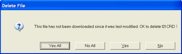
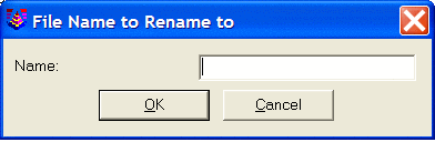
Rename: To rename a file, click on the file to rename and select the rename button at the button of the dialog. On the dialog that displays type in the new name and press the OK button.
Options: This command allows you to set various options
for data transfer. The dialog shown below will appear.
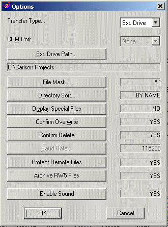
Transfer Type: Choose USB for transferring over a USB
cable. Choose 9-Pin for transferring over a 9-pin serial cable.
Choose Ext Drive for transferring to another folder on your
computer or a drive connected to your computer such as a USB
storage drive or memory card.
Com Port: You must select which com port on the PC to use
when using the 9-Pin transfer type.
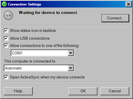
If you are transferring data via a USB port, set the com port to
ActiveSync, see the Options section below for procedures to change
com ports. To transfer data using an USB port a connection
between the Remote and PC using ActiveSync is required. In
ActiveSync verify that the "Connect Settings" have been set
to "Allow serial cable or infrared connection to this Com
port" and Allow USB connection with this desktop computer. This
will allow for connection using an USB port or a COM port
connection. Both will use ActiveSync to transfer data between
devices.
File Mask: You must select a file filtering syntax. This
filter allows for the setting of specific file types to display.
For example if you only wanted to see CRD files the filter would be
*.CRD.
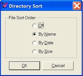
Directory Sort: You must select how to sort the list of
files.
Display Special Files: Toggle whether or not you should
see special files.
Confirm Overwrite: Check this to confirm before overwriting
files.
Baud Rate: You must choose the baud rate for transferring
data.
Protect Remote Files: Check this to protect files on the
mobile device.
Archive RW5 Files: With
this option set to YES, when downloading rw5 files, a second copy
of the file will be made with a .SC5 extension to serve as an
archive of the original rw5 file.
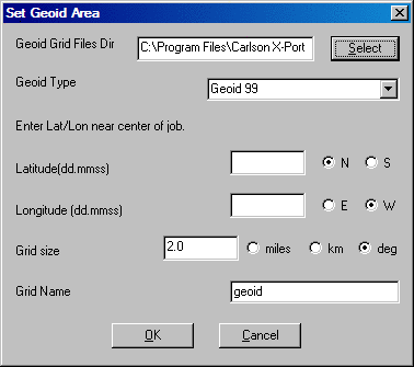
Geoid: This command will carve out a portion of the Geoid 99, EGM96, Canadian CGC2000, Canadian HT2.0, Canadian HT 1.01, Australian GDA94, Great Britain OSG-MO2 and Geoid 2003 grid files, and send it to SurvCE. Since these geoid grids are very large, this carves out a precise portion of it and avoids overloading the memory on the remote device running SurvCE. You will be prompted for the directory on the PC of the source Geoid grid file, the approximate latitude and longitude of the job, and the size of the area desired in miles, kilometers or degrees of latitude and longitude. To define a Geoid area, make sure that this criteria is met:
1. Specify the location of the geoid grid files.
2. Specify the geoid type.
3. Enter the latitude and longitude near the center of the job area.
4. Specify the Grid size either in miles, km (kilometers), or deg (degrees).
5. Name the grid file.
The file will be transferred to the data collector and place in the appropriate place for use.
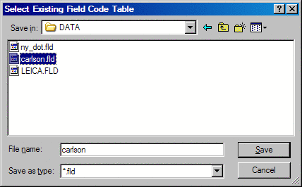
F2F conv: This converts the more thorough and detailed
Carlson field code file (for field-to-finish work, *.FLD) to the
more simplified Feature Code List that runs in SurvCE (*.FCL). The
Feature Code List in SurvCE (not SurvStar or Field) handles
Linework (on or off), Line Type (2D or 3D), Layer (= Code) and Full
Text (Description). Select the Carlson field code (*.FLD) to
convert, the conversion takes place and the file is transferred and
located in the correct location for use in the data
collector.
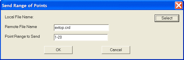
Send Pnts: This option allows for the uploading of a user
specified point number range out of the selected crd file to
unload. Use the Select button to specify the crd file to upload.
The Remote File Name will default to the name of the crd file
selected to upload. You can change this name if needed. Specify the
Point Range to Send and select the OK button.
Exit: This command will exit the File Transfer
Utility
The following information describes the buttons on the Data Collection Programs dialog box that come after the Carlson SurvCE button, moving from left to right and then from top to bottom. The command/button name is on the far left margin, in bold:
Prepare Geoid for
SurvCE
This function creates a .GSF (Geoid Separation File) for SurvCE
from a built-in geoid. Most geoids are very large and this routine
carves out a subset of the geoid by specifying a center position
and area size. The geoid data files are not included in the regular
install since they are so large. Instead, the program automatically
downloads them as needed from the Carlson server. You can also
install them separately by running the CarlsonGeoidGrids.exe from
the Support->Other Downloads on www.carlsonsw.com.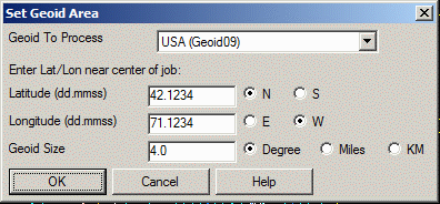
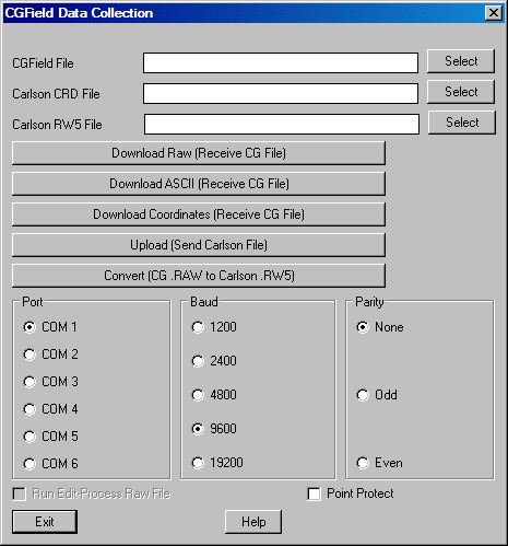
CG Field
To transfer data to and from data collectors using CGField
software, first make sure that the Baud Rate is set to 9600 and the
Parity is set to NONE then follow the steps outlined
below.
Receiving a Coordinate File from CGField
CGField:
1) Go to the UTILS menu
and select Option 1, C&G Transfer.
2) Select Option 4, “Send Coords”
3) Select the Coordinate file to send.
Stop here in CGField and go to
Carlson.
Carlson:
Leave the FILE fields blank.
Press the “Download Coordinates”
button to ready Carlson to receive the file.
Stop here in Carlson and go back to CGField to
complete the transfer process.
CGField:
Select the points to send
1) For All points
2) To select Blocks of points.
3) From .PTS file (the set of points in a
Batch Point File).
The coordinates will be
transferred. After the transfer is complete, you will be asked for
the CRD file name. The C&G CRD file will automatically be
converted to a Carlson CRD file. With Point Protect on, the routine
will check the coordinate file for existing point data
before downloading the point
from the data collector.
Receiving a Raw Data File from CGField
CGField:
1) Go to the UTILS menu
and select Option 1, C&G Transfer.
2) Select Option 2, “Send Raw Data”. Stop
here in CGField and go to Carlson.
Carlson:
Leave the FILE fields blank.
Press the “Download Raw” button
to ready Carlson to receive the file. Stop here in Carlson and go
back to CGField.
CGField:
Select the raw data file to be sent. The transfer will begin.
The C&G .RAW file will be transferred and saved in the data folder. After the transfer is complete, you will be asked for the RW5 file name. The RAW file will be automatically converted to a Carlson RW5 file.
Receiving an ASCII file from CGField
This will allow you to transfer a C&G report file (RPT) or an ASCII NEZ file to Carlson.
CGField:
1) Go to the UTILS menu
and select Option 1, C&G Transfer.
2) Select Option 6, “Send ASCII”. Stop
here in CGField and go to Carlson.
Carlson:
Leave the FILE fields blank.
Press the “Download ASCII”
button to ready Carlson to receive the file. Stop here in Carlson
and go back to CGField.
CGField:
Select the ASCII file to send.
After the transfer is complete,
you will see the file in the Carlson editor. You can then select
FILE and SAVE (or SAVEAS) to save the ASCII file.
Sending a Coordinate File to CGField
CGField:
1) Go to the UTILS menu
and select Option 1, C&G Transfer.
2) Select Option 3, “Receive Coords” to
ready the data collector. Stop here in CGField and go to
Carlson.
Carlson:
Leave the FILE fields blank.
1) Press the “Upload (Send
Carlson File)” button.
2) Select the Coordinate file.
3) Select the points to send.
4) Press the “Start Transfer”
button.
CGField:
Carlson will send the file name to CGField and a coordinate file with the same name will be automatically created or opened in CGField.
If the file exists you will be asked how you want to handle duplicate points:
1) Overwrite
2) Don’t Overwrite
3) Ask for each Point
The point transfer will begin.
Convert CG .RAW to Carlson .RW5
This utility allows you to convert a C&G raw data file to a Carlson raw data file. Select the C&G .RAW file to convert. Then enter the file name of the destination Carlson RW5 file.
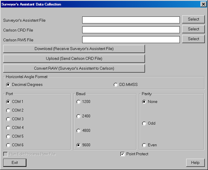
Thales/FastSurvey You will be taken directly to the SurvCOM dialog, similar to the Carlson SurvCE process.Download
From the Surveyor's Assistant data collector, go to the Transfer
routine from the main menu. Fill out the transfer screen as
follows:
Direction: OUTPUT
Format: LIETZ
Data: Coordinate or All Data
Port: COM1 or COM2 Ckh Hold: NO
Protocol: NONE
You should also check the settings under the PORT menu. Typical
port settings are baud=9600, parity=none, data=8, stop=1 and
handshake=XON/XOFF. Now in Carlson, run Data Collection in
the Survey menu and choose Surveyor's Assistant. Check that the COM
port and baud rate are set correctly. Then click the Download
button and within 10 seconds go back to Surveyor's Assistant and
press GO. The file transfer should now go. If the All Data option
is used, then the Leitz format will contain both coordinate and raw
data. The coordinate data is converted to a Carlson coordinate
(.CRD) file and the raw data is converted to a Carlson raw data
(.RW5) file. When the transfer is complete, the program will ask
you for the Carlson coordinate (.CRD) file to create if you haven't
already specified a file name in the dialog. With Point Protect on,
the routine will check the coordinate file for existing point data
before downloading the point from the data collector.
Upload
Point data from the Carlson coordinate (.CRD) file can be uploaded
into the Surveyor's Assistant. First go to the Transfer routine on
the main menu. Fill out the screen as follows:
Direction: INPUT
Format: LEITZ
Port: COM1 or COM2
Protocol: NONE
Go back to Carlson and choose Surveyor's Assistant from the
Data Collection command in the Survey menu. Check that the
COM port and baud rate are set correctly. In the Carlson dialog,
pick the Select File button next to the Carlson coordinate (.CRD)
File edit box and choose the coordinate (.CRD) file to send. Then
click the Upload button. A dialog now allows you to specify the
range of point numbers to upload. Before clicking the OK button for
range of points, go to the Surveyor's Assistant and hit the GO
function key. The Surveyor's Assistant is now waiting to receive so
return to Carlson and click OK on the range of point dialog. The
file transfer should now go.
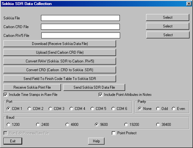
This routine applies to the Sokkia SDR-20, SDR-22, SDR-31 and SDR-33 as well as other collectors that have SDR format transfer such as the Trimble and C & G.
Download
From the SDR data collector, go to the Communications routine from
the main menu. Choose Data Format SDR. Next hit the Send function
key. Then choose Select Jobs. From the list of jobs, highlight the
job to transfer and set it to Yes with the arrow keys. Now in
Carlson, run Data Collection in the Survey menu and choose
Sokkia/SDR. Check that the COM port and baud rate are set
correctly. Then click the Download button and within 10 seconds go
back to SDR and press OK. The file transfer should now go. The SDR
format contains both coordinate and raw data. The coordinate data
is converted to a Carlson coordinate (.CRD) file and the raw data
is converted to a Carlson raw data (.RW5) file. The original SDR
transfer file is stored on the computer as a RAW file. When the
transfer is complete, the program will ask you for the Carlson
coordinate (.CRD) file to create if you haven't already specified a
file name in the dialog. With Point Protect on, the routine will
check the coordinate file for existing point data before
downloading the point from the data collector.
The SDR-33 has different modes for storing and transferring
data. In coordinate mode, the download will create points in the
coordinate (.CRD) file and the raw data (.RW5) file will only
contain some basic header lines. In the raw data mode, the download
will create all the measurement data in the raw file and no points
will be created in the coordinate (.CRD) file. For this raw data
mode, you will need to run Edit-Process Raw Data File
in the Survey menu to calculate the points from the raw data. The
third mode in the SDR-33 creates both raw data in the raw data
(.RW5) file and points in the coordinate (.CRD) file. The Include
Time Stamps in Notes option sets whether all the date-time records
for each point are put in the raw data (.RW5) file as description
records. The Include Point Attributes in Notes option will store
SDR code 13(AT) codes to the point note (.NOT) for the coordinate
(.CRD) file.
Upload
Point data from the Carlson coordinate (.CRD) file can be uploaded
into the SDR. First go to the Communications routine on the SDR
main menu. Choose Data Format SDR. Go back to Carlson and choose
Sokkia/SDR from the Data Collection command in the Survey
menu. Check that the COM port and baud rate are set correctly. In
the Carlson dialog, pick the Select File button next to the Carlson
CRD File edit box and choose the coordinate (.CRD) file to send.
Then click the Upload button. Then a Sokkia Options dialog appears
for setting the job parameters for the file to be created on the
collector. Be sure to choose the Distance Unit that matches your
coordinate (.CRD) file (meters, US feet or international feet).
Click OK and the next dialog now allows you to specify the range of
point numbers to upload. Before clicking the Start Transfer button
for range of points, go to the SDR and hit the Receive function
key. The SDR is now waiting to receive so return to Carlson and
click Start Transfer on the range of point dialog. The file
transfer should now go.
Communication Settings
Besides matching the baud rate between Carlson and the collector,
make sure that the collector is set to word length of 8 and 1 stop
bit under the communication settings.
Print File
The Receive Sokkia Print File downloads a print report from the
SDR33 data collector. This file is only used for printing report
purposes in Carlson. This file is not used by Carlson to generate
coordinate (.CRD) files or raw files. The first step is to choose
Data format=Printed in the Communications menu of the SDR33. Next
pick the Receive Print File button in Carlson. Then on the SDR33
choose the Send function and select a job to send. At this point
the file is transferred. After downloading, the job report is
displayed in the Carlson standard
report viewer.
Example of
Sokkia Printed Format:
SDR33 V04-04.25 (C) Copyright 1998 Sokkia May-29-80 23:39 01/29/1999

            Angle Degrees        Dist Feet

              Temp Farenht         Coord N-E-Elev

JOB              TRAV                 Point Id Alpha (14)

            Atmos crn No         C and R crn No

         Record elev Yes      Sea level crn No

POS TP 1       North 10050.000      East 10000.000        Elev 0.000

POS TP 2       North 10000.000      East 10000.000        Elev 0.000

POS TP 3       North 9515.636       East 9551.975         Elev 37.611

              Code T3

POS TP 403   North 4967.527       East 5074.632         Elev 0.000

NOTE TS        Jan-01-80 00:14

** End of report **
Download [HP-48 and Husky]
In the TDS program, go to the File Transfer routine. Choose the
type of data to transfer (CRD or RAW). Next pick the Send function
key. Stop here on the TDS and go to Carlson to run Data
Collection in the Survey menu and pick TDS. Make sure that the
COM port and baud rate are set correctly. Then pick the Download
button. The Carlson program will now wait to receive the TDS file.
Within 10 seconds select the file to send on the TDS. The file
should be transferred now. When the transfer is complete, the
program will ask you for the Carlson file to create if you haven't
already specified a file name in the dialog. With Point Protect on,
the routine will check the coordinate file for existing point data
before downloading the point from the data collector.
Download [Ranger and Windows CE]
In the TDS program, go to the Transfer routine and pick the Send
File function. Set the "Connecting To" field to HP-48. Make sure
that the COM port, baud rate and parity are set correctly and then
pick OK. In the Type field of the file selection dialog, choose
Coordinate Files or Raw Files. Stop here on the TDS and go to
Carlson to run Data Collection in the Survey menu and pick
TDS. Make sure that the COM port and baud rate are set correctly.
Then pick the Download button. The Carlson program will now wait to
receive the TDS file. Within 10 seconds select the file to send on
the TDS and pick OK in the TDS dialog. The file should be
transferred now. When the transfer is complete, the program will
ask you for the Carlson file to create if you haven't already
specified a file name in the dialog. With Point Protect on, the
routine will check the coordinate file for existing point data
before downloading the point from the data collector.
Upload [HP-48 and Husky]
A Carlson coordinate (.CRD) file can be converted to a CR5 file and
uploaded into TDS. Start in the TDS program, by going to the File
Transfer routine. Then move back to Carlson and run Data
Collection in the Survey menu and pick TDS. In the Carlson
dialog, enter a TDS File name. This name should not include the
drive and directory path or file extension. For example, if the
coordinate (.CRD) file is c:\scadxml\data\simo2.crd then the TDS
File name could be just SIMO2. Next pick the Select File button
next to the Carlson coordinate (.CRD) File edit box and choose the
coordinate (.CRD) file to send. Check that the COM port and baud
rate are set correctly. Now pick the Carlson Upload button. A
dialog now allows you to specify the range of point numbers to
upload. Enter the range of points but before clicking the Start
Transfer button go to TDS and hit the Receive function key. Within
10 seconds go back and click the OK button on the range of points.
The file should then transfer.
Upload [Ranger and Windows CE]
A Carlson coordinate (.CRD) file can be converted to a CR5 file and
uploaded into TDS. Start in the TDS program, by going to the
Transfer routine and pick the Receive File function. Set the
"Connecting To" field to HP-48. Make sure that the COM port, baud
rate and parity are set correctly and then pick OK. Then move back
to Carlson and run Data Collection in the Survey menu and
pick TDS. In the Carlson dialog, enter a TDS File name. This name
should not include the drive and directory path or file extension.
For example, if the coordinate (.CRD) file is
c:\scadxml\data\simo2.crd then the TDS File name could be just
SIMO2. Next pick the Select File button next to the Carlson
coordinate (.CRD) file edit box and choose the coordinate (.CRD)
file to send. Check that the COM port and baud rate are set
correctly. Now pick the Carlson Upload button. A dialog now allows
you to specify the range of point numbers to upload. Enter the
range of points and click the Start Transfer button.
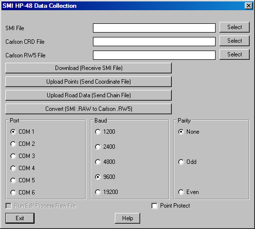
Download
To send point data from the SMI data collector, go to the file
transfer routine by typing [More] [NXT] [TOPC] [COMM]. In SMI
version 6 or later, type [Job][KERM][SEND]. Also in version 6, make
sure that the first function key reads [NE] and not [XY] in the
[Job][KERM] screen. Otherwise the coordinate northing and easting
will be reversed. The [NE] stands for North-East coordinate order
which is the format that Carlson expects. Also in the [Job][KERM]
screen, make sure that the second function key reads [COMM] and not
[SPACE]. The [COMM] stands for comma separators. Then enter the
first point to send followed by the last point to send but before
pressing Enter for the last point go to Carlson. Run Data
Collection in the Survey menu and choose SMI. Check that the
COM port and baud rate are set correctly. Then click the Download
button and within 10 seconds go back to SMI and press Enter for the
last point to send. The file transfer should now go. When the
transfer is complete, the program will ask you for the Carlson
coordinate (.CRD) file to create if you haven't already specified a
file name in the dialog. With Point Protect on, the routine will
check the coordinate file for existing point data before
downloading the point from the data collector. To send raw data,
use the [Print][Raw] routine in SMI along with the same Carlson
procedure used for point data.
Upload
From the SMI data collector, go to the file transfer routine by
typing [More] [NXT] [TO48] [COMM]. In SMI version 6 or later, type
[Job][KERM][RECV]. Also in version 6, make sure that first function
key reads [NE] and not [XY] in the [Job][KERM] screen. Otherwise
the coordinate northing and easting will be reversed. Then enter
the first point to send followed by the last point to send. Next
enter the job name but before pressing Enter go to Carlson and run
SMI under Data Collection in the Survey menu. In the Carlson
dialog, specify the same job name as entered in SMI. Next pick the
Select File button next to the Carlson CRD File edit box and choose
the coordinate (.CRD) file to send. Check that the COM port and
baud rate are set correctly. Then click the Upload button. A dialog
now allows you to specify the range of point numbers to upload.
Enter the same range of points as entered on the SMI. Go back to
SMI and hit Enter for job name followed by clicking the OK button
for range of points in Carlson. The file transfer should now
go.
There are three types of Leica transfers: GIF-10, GeoCom and
DBX.
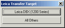 Choose newer Leica instruments,
choose Leica DBX on first dialog. Then there is a choice between
Import and Export.
Choose newer Leica instruments,
choose Leica DBX on first dialog. Then there is a choice between
Import and Export.
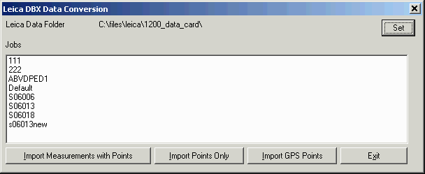
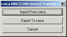 For Import,
select the folder that contains the Leica DBX data. Typically the
Leica DBX data is on a memory card that is inserted into the
computer and gets assigned a drive name by Windows. Use the Set
button to browse to this Leica DBX drive or folder. Then the
program shows a list of the Leica projects in that folder. The
Import Measurements With Points function reads the Leica data into
Carlson CRD and RW5 files. The Import Points Only reads the Leica
data into a Carlson CRD file and brings in attribute data to the
Carlson NOT file. The Import GPS Points function imports the Leica
data into a Carlson RW5 file for GPS measurements.
For Import,
select the folder that contains the Leica DBX data. Typically the
Leica DBX data is on a memory card that is inserted into the
computer and gets assigned a drive name by Windows. Use the Set
button to browse to this Leica DBX drive or folder. Then the
program shows a list of the Leica projects in that folder. The
Import Measurements With Points function reads the Leica data into
Carlson CRD and RW5 files. The Import Points Only reads the Leica
data into a Carlson CRD file and brings in attribute data to the
Carlson NOT file. The Import GPS Points function imports the Leica
data into a Carlson RW5 file for GPS measurements.
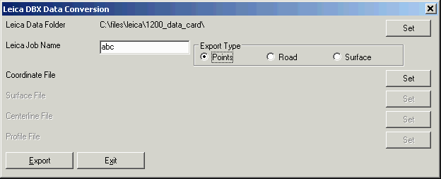
 For Export, select the folder to
store the Leica DBX data to using the Set button. Enter in a job
name for the new job in the Leica Job Name edit box. There are
three types of project data that can be exported. The Points export
converts a Carlson coordinate file to Leica format. The Road export
converts Carlson profiles and centerlines to Leica format. The
Surface export converts a Carlson TIN file to Leica format.
For Export, select the folder to
store the Leica DBX data to using the Set button. Enter in a job
name for the new job in the Leica Job Name edit box. There are
three types of project data that can be exported. The Points export
converts a Carlson coordinate file to Leica format. The Road export
converts Carlson profiles and centerlines to Leica format. The
Surface export converts a Carlson TIN file to Leica format.
For GIF-10 and GeoCom, choose All Others on the first dialog
Then the choice for GIF-10 or GeoCom is set in the Equipment
Type field on the main dialog. For transferring with the Leica
instruments, the GeoCom program shows a dialog of the available COM
ports on your computer. On the first time that you transfer to an
instrument, you will need to pick the Instruments button and
register the instrument from the list. Pick the Port Settings
button to make sure that the communication settings match the
instrument.
 To download
a file with GeoCom, make sure that the instrument is ON and
connected to the computer by serial cable. The instrument also
needs to be in GeoCom mode. Then pick the Download in the Carlson
dialog. In the GeoCom program, open the computer COM port that the
instrument is connected to by picking the '+'. Then open the Memory
Card and GSI folders. Next select the file to transfer and click
the OK button. With Point Protect on, the routine will check the
coordinate file for existing point data before downloading the
point from the data collector.
To download
a file with GeoCom, make sure that the instrument is ON and
connected to the computer by serial cable. The instrument also
needs to be in GeoCom mode. Then pick the Download in the Carlson
dialog. In the GeoCom program, open the computer COM port that the
instrument is connected to by picking the '+'. Then open the Memory
Card and GSI folders. Next select the file to transfer and click
the OK button. With Point Protect on, the routine will check the
coordinate file for existing point data before downloading the
point from the data collector.
To upload a file with GeoCom, specify the file name to be created on the instrument in the Leica File field and pick the Upload button in the Carlson dialog. Then the program will prompt for the range of points to transfer. Fill out the range and pick the Start Transfer button. Then the GeoCom program will start. Open the computer COM port by picking the '+'. Then open the Memory Card folder and highlight the GSI folder and click OK.
The upload and download file transfer works with the GIF-10 data collector. The GIF-10 communication settings should be the following:
Baud: 9600
Parity: NONE
Protocol: NONE
Stop Bit: 1
End Mark: CR/LF
Connected As: Some computers use DCE and others use DTE
Download
From the GIF-10, go to the file transfer routine. Then go to
Carlson and run Data Collection in the Survey menu and
choose Leica. Check that the COM port and baud rate are set
correctly. Then click the Download button and within 10 seconds go
back to GIF-10 and select the file to send. The file transfer
should now go. When the transfer is complete, the program will ask
you for the Carlson coordinate (.CRD) file to create if you haven't
already specified a file name in the dialog. With Point Protect on,
the routine will check the coordinate file for existing point data
before downloading the point from the data collector.
Upload
From the GIF-10 data collector, go to the file transfer routine.
Then go to Carlson and run Leica under Data Collection in
the Survey menu. In the Carlson dialog, specify the job name in the
Leica File field. Next pick the Select File button next to the
Carlson coordinate (.CRD) File edit box and choose the coordinate
(.CRD) file to send. Check that the COM port and baud rate are set
correctly. Then click the Upload button. A dialog now allows you to
specify the range of point numbers to upload. Before clicking the
OK button for range of points, go to GIF-10 and start the receive
by highlighting Receive and pressing the Run button. The GIF-10 now
shows the available job numbers. Choose a job to receive the
transfer using the arrow buttons and then press the Run button.
Converting
Carlson supports raw and coordinate data collected using three
different Leica Operation Codes: Wildsoft and 10-20-30-40 as well
as the newer LISCAD. Moreover, data could be in the GSI8 format or
the newer GSI16 format. Some example files are shown here.
GSI8 format data file using LISCAD Operation
codes:
WILD GIF-12
410149+00000001 42....+00005003 43....+00005.42 44....+00005.25
45....+00005000
110150+00005000 21.324+35959480 22.324+09238590 31..01+00228271
410151+00000005 42....+00010100
110152+00005001 21.324+35156390 22.324+09303500 31..01+00133532
410153+00000005 42....+00070100
410154+00000014 42....+00000ELM
110155+00007082 21.324+34739450 22.324+09322050 31..01+00137685
410156+00000005 42....+00070102
GSI16 format data file using LISCAD Operation
codes:
*110001+0000000000000001 84..11+0000010000000000
85..11+0000003000000000
86..11+0000000001000000 87..11+0000000000005170
*410002+0000000000000009 42....+0000000000000001
43....+000010000000.000 44....+000003000000.000
45....+000000001000.000
*410003+0000000000000001 42....+0000000000000001
43....+000000000005.330 44....+000000000000.000
*410004+0000000000000004 42....+00000000178.1530
*410005+0000000000000003 42....+0000000000000002
43....+0000000000000001
*110006+00000000000000RO 21.324+0000000017815300
22.324+0000000008424260
31..01+0000000000000000
*410007+0000000000000100
*410008+0000000000000012 42....+000000000005.090
*110009+0000000000000002 21.324+0000000000831230
22.324+0000000008130270
31..01+0000000000089996
*110010+0000000000000002 21.324+0000000018831230
22.324+0000000027829250
31..01+0000000000089996
*110011+00000000000000RO 21.324+0000000035815170
22.324+0000000027539300
31..01+0000000000000000
GSI8 format data file using Wildsoft Operation
codes:
410001+00000001 42....+00000013 43....+00000000 44....+00000012
45....+00981101
410002+00000002 42....+00000013 43....+00005.42 44....+00000012
45....+00000000
410003+00000032 42....+00000500 43....+00004.26 44....+00000012
45....+00000000
410004+000000TP 42....+00000000 43....+00000000 44....+00000000
45....+00000000
110005+00000501 21.124+00000000 22.104+09136260 31...1+00000000
51..0.+0012+000
110006+00000502 21.124+03741320 22.104+08915570 31...1+00246818
51..0.+0012+000
110007+00000503 21.124+03915180 22.104+08919040 31...1+00251956
51..0.+0012+000
110008+00000504 21.124+06530420 22.104+08839360 31...1+00113998
51..0.+0012+000
Leica raw files usually have a .RAW or .GSI extension. The primary difference in the GSI8 and GSI16 formats is that information is contained in data blocks of 16 characters in the GSI16 format, while it is contained in blocks of 8 characters in the GSI8 format. Leica instruments make it possible to have both the GSI8 as well as GSI16 data formats in the same raw file. However, lines with the GSI16 format data will always start with an asterisk (*) character, to distinguish them from the GSI8 format. There is no distinction between Leica raw files collected in the Wildsoft and LISCAD operation codes.
Supported Wildsoft codes:
1: Start Job
11: Assign Coords
12: Coord Offset
13: Target Height
14: Add to Tgt Ht
15: Add to Meas Dist
2: Occupy Point
21: Occupy Saved Point
3: FS to Trav Pt
31: FS to Single Pt
32: Radial Sideshots
33: Sets of Angles
4: Closing Pt
41: Closing Angle
50: BS to Benchmark
51: FS to Turn Pt
52: BS to Turn Pt
53: FS to Benchmark
60: Save Point
61: Recall Point
62: Compare Point
63: Remark
Supported LISCAD codes:
1: New instrument
setup
2: New target height
3: Sets of directions
4: Fixed azimuth
5: Feature code
6: Measured offset
8: Line creation for sub-codes 1 (straight string), 2 (curved
string) and 6 (arc by 3 points)
9: Fixed coordinates
11: Close string
14: Additional description
20: Start of job
27: Feature code
90: Split feature code
100+: Descriptions
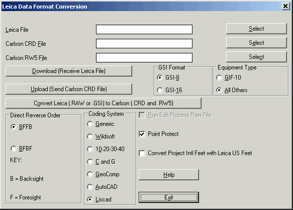
The Convert button can be used to convert any Leica format file
into a Carlson format file. For example, if you have a Leica PCMCIA
card then there is no serial cable transfer to do. Instead use the
Convert routine to make the Carlson raw data (.RW5) and coordinate
(.CRD) files. Since there is no distinction between Wildsoft and
LISCAD files, the user must know in advance which format has been
used in the file. Then, select that particular option (Wildsoft,
10-20-30-40 or LISCAD) under the "Coding System" option at the
bottom of the dialog box, as shown in the previous page. Another
option that the user needs to choose is the order in which
foresight-backsight readings have been recorded in the raw file,
BFFB or BFBF, as explained in the dialog box. Then, the user can
simply pick the "Convert" button and the program prompts for the
input" Wild/Leica File" (raw file), and the output" Carlson RW5
file" and "Carlson CRD file", if they are not already
filled.
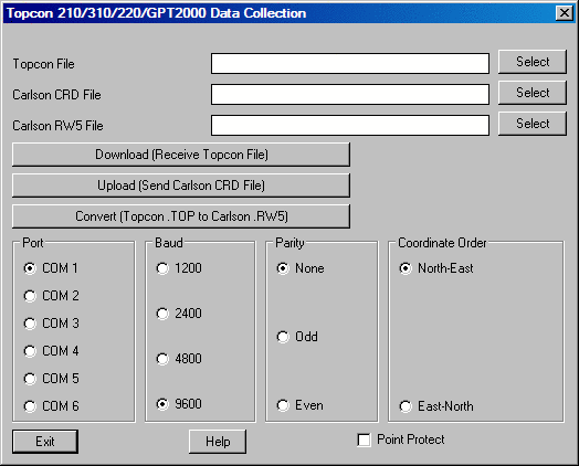
Download
First choose the equipment and data type under the Transfer Type
list. Also check that the communication and data format settings
match your collector. Then click the Download button and follow the
on-screen directions. When the transfer is complete, the program
will ask you for the Carlson coordinate file (.CRD) and raw file
(.RW5) to create if you haven't already specified a file name in
the dialog. With Point Protect on, the routine will check the
coordinate file for existing point data before downloading the
point from the data collector. The original data from the collector
is stored in a file name with the same name as the coordinate file
except with a .TRN extension. For example, job5.crd would have
job5.trn.
Upload
Pick the Select File button next to the Carlson CRD File edit box
and choose the CRD file to send. Check that the COM port and baud
rate are set correctly and then click the Upload button. A dialog
now allows you to specify the range of point numbers to upload. Set
the points and then click the Start Transfer button. The file
transfer should now go.
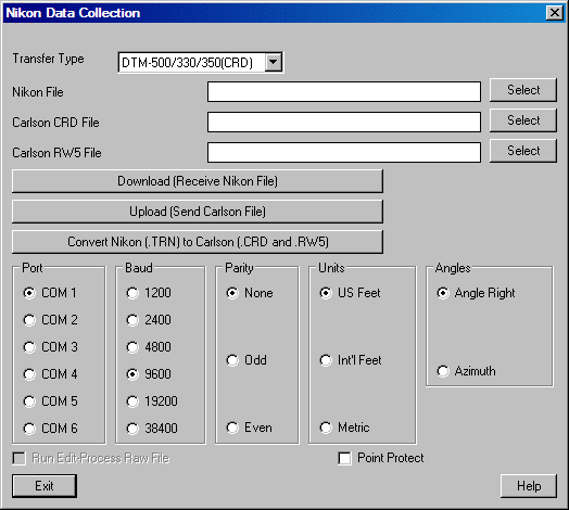
Convert Nikon to Carlson
The Convert button will translate the Nikon raw file format (.TRN
or .RAW) into Carlson coordinate (.CRD) and raw (.RW5) files.
Portion of typical Nikon file
format:
MP,1,,5000.0000,5000.0000,0.0000,T/1
CO,31-Oct-1999 11:42:38
ST,1,,2,,0.0000,0.00000,0.00000
SS,3,0.0000,152.1510,359.59590,90.44100,11:43:38,T/2
SS,4,0.0000,127.5560,0.06040,90.40110,11:44:45,CON
SS,5,0.0000,97.1820,2.19580,90.52460,11:45:43,CON
Download
From the Geodimeter data collector, go to the file transfer routine
by pressing the PRG (Program) key and entering program 54. Then
choose Imem (option 1) as the source. Next choose the file type to
send as either Job (measurement data) or Area (point data). The
Geodimeter will then prompt for the job name. Next enter Serial
(option 3) as the destination. A confirmation screen appears
showing the serial port settings. Here are some typical
settings:
COM=1,8,0,9600
Before pressing enter (ENT key), go to Carlson and run Data
Collection in the Survey menu and choose Geodimeter. Then click
the Download button and within 15 seconds, go back to the
Geodimeter and press Enter. The file transfer should now go. When
the transfer is complete, the program will ask you for the Carlson
coordinate file and raw file to create if you haven't already
specified a file name in the dialog. With Point Protect on, the
routine will check the coordinate file for existing point data
before downloading the point from the data collector.
Upload
In Carlson, run Geodimeter under Data Collection in the
Survey menu. Pick the Select File button next to the Carlson CRD
File edit box and choose the CRD file to send. Check that the COM
port and baud rate are set correctly and then click the Upload
button. A dialog now allows you to specify the range of point
numbers to upload. Enter the points to send but before clicking OK,
go to the Geodimeter data collector. Start the file transfer
routine by pressing the PRG key and entering program 54. Then
choose Serial (option 3) as the source. The Geodimeter will display
the serial port settings. Check these values and press enter. Next
choose Area (option 2) as the destination. Then enter the job name.
The Geodimeter is now listening for data. Quickly go back to
Carlson and click OK on the points to send dialog. The file
transfer should now go
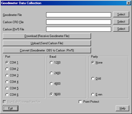
Convert
The Convert button will translate the Geodimeter raw file format
(.OBS) into Carlson coordinate (.CRD) and raw (.RW5) files.
Communication Settings
If the Geodimeter is not communicating with Carlson, run function
79 on the Geodimeter and make sure that it is set to 4. This
setting is for the transfer message end of sequence format.
Supported Geodimeter Codes
The following Geodimeter
codes are processed when converting the Geodimeter raw file. All
other codes are recorded as descriptions in the Carlson rw5
file.
0=Info
1=Data
2=Station No
3=Instrument Height
4=Point Code
5=Point Number
6=Signal Height
7=Horizontal Angle
8=Vertical Angle
9=Slope Distance
11=Horizontal Distance
17=Horizontal Angle
18=Vertical Angle
21=Horizontal Reference Angle
30=Atmospheric Correction
37=Northing
38=Easting
39=Elevation
40=Delta North
41=Delta East
42=Delta Elevation
45=Correction To Bearing
46=Standard Deviation
50=Job Number
51=Date
52=Time
53=Operator
54=Project Id
55=Instrument Id
56=Temperature
60=Shot Id
61=Activity Code
62=Reference Object
70=Entered Radial Offset
71=Entered Angle Offset
72=Calculated Radial Offset
73=Calculated Angle Offset
74=Air Pressure
Portion of typical Geodimeter
file format
5=108
4=13POC
6=5.000
7=238.0708
8=89.2236
9=440.39
37=767.42
38=4626.07
39=699.795
This command supports these above Topcon models.
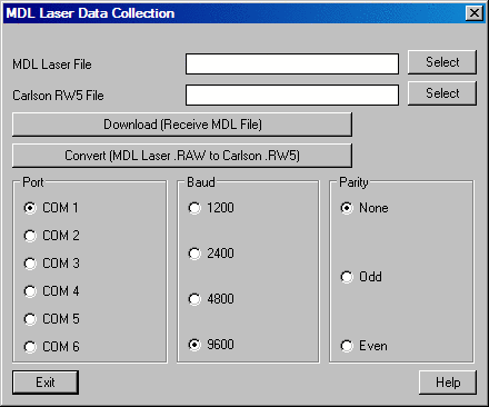
The MDL Laser outputs a raw file of angles, distances and codes
as one long string of data which can be converted into a Carlson
raw data (.RW5) file. There is no coordinate data in the MDL raw
file. So you need to run Edit-Process Raw File to calculate
coordinates from the raw data. The Download button will transfer
the MDL raw data from a BDI logger.
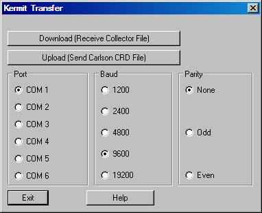
Kermit can be also used for transferring files with accuracy.
The dialog looks like this:
Pulldown Menu Location:
Survey
Keyboard Command: datacolt
Prerequisite: None