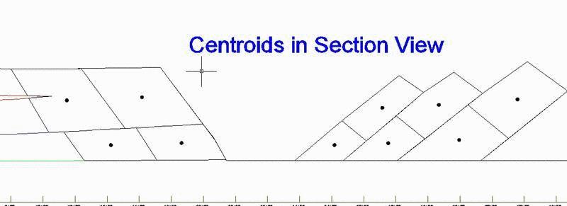
This command draws a point at the centroid of a closed polyline,
a grid surface or a solid model. In case of cross sections, the
areas need to be closed polylines representing the blocks to
calculate the centroids of. This is useful for calculating haul
distances and blast distances in section view. When choosing to
come from a grid file, it finds the x,y position for the center of
mass. Typically this grid would be the difference between existing
and design surfaces, represented as a thickness grid. For example,
this routine could be used to find the center of mass for a
stockpile using a difference grid of the stockpile grid and base
grid. For a solid model, the routine calculates the 3D centroid for
the volume of the solid. The solid needs to be a watertight shell.
The solid model is loaded from a MDL file.
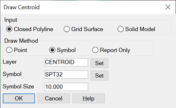
The Draw Method controls the output for the centroid. You can draw a CAD point or a symbol at the centroid, or only report the centroid coordinates.
Draw Centroid
Dialog
Select closed
polyline(s).
Select
objects: 1 found
Select objects:
Center at
1462284.64,1971935.94
Pulldown Menu Location: Surface
Keyboard Command: plcenter
Prerequisite: Closed polylines or a .GRD file