Design Bench Pit
This command creates pits where the sides are a series of slopes
with benches. The side slopes start from a closed polyline. This
pit polyline can be either the bottom of the pit and the slopes run
up and out to intersect the ground surface, or the pit polyline can
represent the top of the pit and the slopes run down and in, to
intersect the pit bottom grid. Different slopes can be used for
different sides of the pit. The pit is drawn as 3D polylines and
the pit volumes are reported.
Before starting this command, the pit perimeter should be drawn
as a closed polyline, 2D at zero elevation, or at 3D elevations on
a surface. The program also needs triangulation or grid files for
the existing ground surface and the bottom of pit surface. Design
Bench Pit starts with the dialog shown below to specify these grid
file names.

- Ground Surface: This is
the surface for the top of pit perimeter.
- Pit Bottom Surface:
This is the surface that will represent the bottom of the pit.
- Pit Bottom Surface By: This option chooses between using
a surface model or fixed Elevation for the target for the bottom of
the pit.
- Write Bench Solids: This option creates solid model
files (.MDL) for the volume of each bench in the design.
- Report Volumes: You can turn off this option to save
processing time if you don't need this routine to report the pit
earthworks.
- Write Surface History
File: This output file is a GSQ file that is used for
volumes in Surface Mine Reserves which leads up to surface mine
timing and scheduling on these volumes, or for 3D Viewing as a
movie with View Surface History File command.
- Round Exterior Corners:
This option will create rounded
corners on the outside edges of the pit for a more realistic
design. When this is off, the corners are sharp and
angular.
- Write Output Grid File:
This option will create a grid file (GRD) of the design. It
includes the original ground surface grid file, with the pits built
onto it.
- Merge Design With Ground: This option combines the bench
pit surface with the existing ground for the output
surface.
- Use
Elevations From Pit 3D Polyline: This will use the elevations on the polyline
as the start of the design. It will start the pits at the elevations the
polylines are drawn at instead of starting at the Pit Bottom Grid
for going up, or the topography when going down.
- Force Bench with Width and Max
Depth: This option applies when
the Slope Method is in Projection mode. This option creates the
bench up to the specified Max Depth beyond the target
surface.
- Process
Multiple Polylines by Pit Names: This option is to process
multiple pit perimeter polylines all at once. The pit polylines
must have pit/site names assigned and the program will process them
in the order of their pit names. As each pit polyline is processed,
the ground surface is updated with the pit volume removed. Then the
next pit will use this updated ground surface. When Process
Multiple is active, the Sequence
Method choose the way to order the pits for processing. The
Pit Name method processes
the pits in alphabetical order. The Timing File method uses the pit
assignment order from Surface Equipment Timing from the .TIM
file.
- Separate
Layers by Pit Names: This option puts the 3D polyline break
lines of each pit on their own separate layer. It takes the Pit
Layer, and increments them by -2, -3 etc.
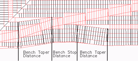
- Create Road: This option carves a rough road into the pit design. In
the dialog, the road Direction, Road Width and Road Slope % are specified along with a
Road Color for the road polylines to create. When
this option is active, the program will prompt for a road starting
point along the pit perimeter. The cut slopes are shifted to make
room for the road. The Bench Stop Distance is for suspending
the bench as it crosses the road to avoid combining the road and
bench widths at the crossing which tends to shift the cut slopes
too much. Within the Bench Stop Distance, the bench has a zero
width. The Bench Stop is centered at the road crossing. The
Bench Taper to the distance that the bench transitions from
full width to zero at the Bench Stop. The Berm Height adds a
berm and makes the road wider to fit the berm. The slope of the
berm is set by the Berm Slope.
- Slope
Direction: Up will start at the pit bottom and bench up and
out to the surface topography. Down will start at the top surface,
and bench down and in to the pit bottom.
- Slope
Method: Projection is a method that projects the 3D
polylines down the slope, across the benches. Offset is a method
that offsets the horizontal "toe and crest" lines to create the pit
shells this way. Both methods will have horizontal and vertical
breaklines, but the method they are generated is different. Each
method has its benefits and might work better than the other for
each unique scenario. If there is a problem with one method, try
the other to see if it handles it better.
- Horizontal & Vertical Interval:
These settings control the
distance to draw the 3D breakline polylines. The horizontal
interval will run down the slope, and across the bench. The
vertical interval will run parallel with the benches. It should be
a factor of the bench height if possible, but not
required.
- Min Bench
Height: The bench is not created when the side slope depth
is less than the specified amount.
- Side Layer: This is the layer of the 3D polylines drawn
perpendicular to the benches, and running down
slope.
- Pit Layer: This layer is applied to the 3D polyline
break lines running parallel to the benches.
- Use Bench Name for Layer Suffix:
This option adds the bench name
to the Pit Layer so that each bench can have a unique name which
can be useful for having different colors for each bench for
visualization or for isolating benches by layer.
- Draw Side Slope Polylines:
This option chooses whether to
draw the 3D polylines running perpendicular to the benches, and
down slope.
- Use Target Surface for Bench Slope:
When the benches use a surface file for the target, this option
makes the bench slope follow the target surface model. Otherwise,
the bench slope is set in the next dialog.
- Bench Color: This setting puts the bench 3D polylines in
the Pit Layer on a different, specified color so they stand out
against the slope breaklines.
- Bench Taper At Surface Tie: When a
bench meets the Ground Surface, this option tapers the bench width
to zero over this specified distance.
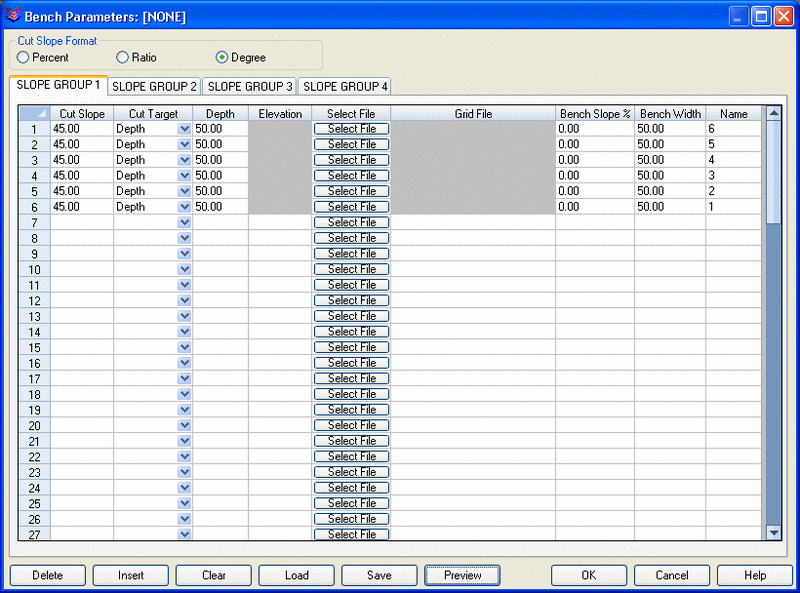
The next dialog defines the cut and bench slopes. Cut
Slopes are entered as ratios. The Cut Target can be
either a fixed depth number, a fixed elevation, a fixed width or to
a grid file. For a grid file, the program will find the
intersection of the cut slope with the grid surface and will end
the cut slope at this intersection. For example, you could make a
grid file for a second coal seam and have the bench occur at this
coal seam. For the width method, the program creates a cut slope to
the target surface with a variable slope to reach the surface at a
fixed cut slope width. This width method can only be used on the
final bench.
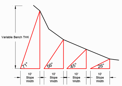
Cut Slope by Width method
After the cut slope, the bench slope and width are used. The cut
and bench slopes are applied in order until there is an
intersection with the surface. Once you have all the cut slopes
defined, you can use the Save button to save these slope settings
to a .PIT file. Then these settings can be recalled later with the
Load button.
The Pick Perimeter For Z Range function prompts to select
a perimeter polyline from the drawing. This function reports the
elevation range of the Ground Surface along this perimeter which is
useful as a reference for setting the bench elevations.
Four different sets of slope schemes can be defined. To define
the another slope scheme, select other Slope Group tab. The set of
slopes that you are currently editing is indicated by the selected
tab. If you define different sets of slopes, then the program will
prompt you to pick which sides to apply each set of slopes to. All
sides are assumed to be slope type one. So you only have to
identify types two, three and/or four. If only one slope group is
defined, then you will not be prompted to select any additional
sides.
If a pit already exists to one side of the current pit, then
this existing pit should be part of the Ground Surface grid file.
Then the program will intersect the surface right away on this side
without creating all the bench-cut slopes.
Here are a couple of examples of the various settings in Design
Bench Pit.
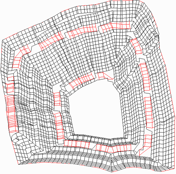
- Offset Method with Road in red:
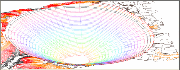
 Projection Method:
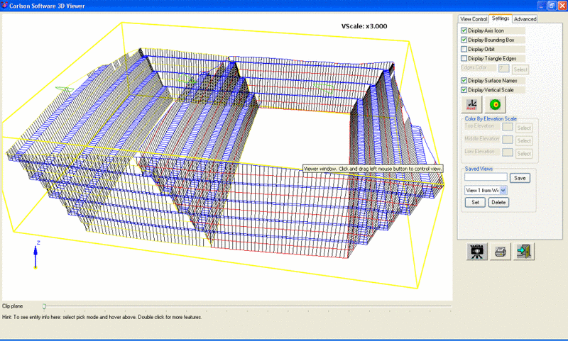
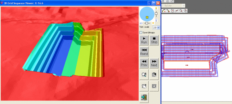
- Multiple Pits with Offset Method and Viewing the Grid
History File in 3D.
 Prompts
Pick the pit polyline: pick the closed
polyline
Pick pit polyline segment for side 2 slopes (Enter to
continue): pick the segment near midway, it will
highlight
Pick pit polyline segment for side 2 slopes (Enter to continue):
pick the segment near midway, it will highlight
Pick pit polyline segment for side 2 slopes (Enter to
continue): press Enter to continue
Pulldown Menu Location: Surface in Surface Mining
Module
Keyboard Command: minepit2