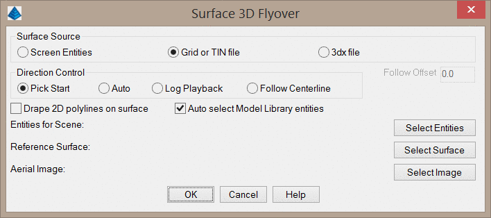
Surface Source: This option sets the source
of the surface to view.
This command allows you to view a 3D surface in a simulated
drive- or fly-over mode. You have the option of following a
predefined path such as a road centerline or using a user-guided
path (free flight). The surface to view can be defined with either
screen entities, surface files, or both. The routine offers options
for different types of surface shading, direction of travel,
viewpoints, vehicles, reference surfaces, light position, color
schemes, vertical exaggeration and more.
Surface Source: This option sets the source
of the surface to view.
Screen Entities: With this option enabled, a surface will be generated from the selected 3D Faces. Other entities such as polylines will only be shown for reference. To select the screen entities, press the Select Entities button.Grid or TIN file: With this option enabled, the surface is defined by either a triangulation file (.FLT or .TIN) or a grid file (.GRD). In addition to the surface file, screen entities may also be selected to be displayed. You will be prompted to select the surface after clicking OK.
3DX File: This method loads the scene from a 3DX file which can be saved from a previous run of Surface 3D FlyOver. Other 3D viewer commands such as the 3D Viewer Window can also save the scene to a 3DX file.
Direction Control: This
option controls the method of movement through the 3D
view.
Pick Start: This option allows the user to randomly navigate the site, but a starting direction must be defined by picking two points on the screen. Once travel starts, the direction can be controlled with the arrow keys on the keyboard.
Auto: This option also allows the user to randomly navigate the site, but a start point is automatically selected.
Log Playback: This option uses vehicle log files from Carlson Machine Control to animate the position of vehicles in the scene and show the surface updates.
Follow Centerline: This method prompts for a centerline file (.CL) or alignment polyline to follow. The camera position of the animation will be limited to follow this alignment. The Follow Offset value shifts the view position to the right (positive value) or left (negative value) of the centerline to simulate driving down one lane of the road.
Drape 2D polylines on
surface: This option will drape 2D polylines onto the
surface regardless of their original elevation.
Auto select Model Library entities: When enabled, this
option will automatically detect 2D symbols in the drawing and
display them as 3D symbols as specified in the 3D
Viewer/Model Library command.
Select Surface (Reference Surface): This button allows
you to select a reference surface file. This will allow you to
report the cut/fill difference between the
given surfaces at the current position. This option is only available when the Surface Source is
set to
Grid or TIN file. Note that this reference surface will not
actually be displayed in the viewer.
Select Image (Aerial Image): This button allows you to drape an aerial image on the surface. This image must be a geo-referenced TIF image that overlaps the area of the surface model. See the Create World File by Image in Drawing for additional information.
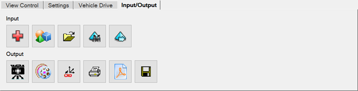
After clicking OK, the 3D graphics window will appear.
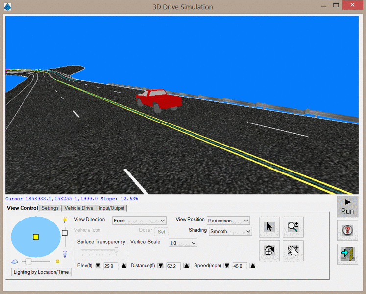
The 3D window has several mouse and keyboard controls that can
assist with navigating the scene. These are listed below:
View Position: This option determines the position of the viewpoint relative to the vehicle. There are three different view positions:
Vehicle Icon: This option determines the type of vehicle to be used in
the display. There are many options available, including dozers,
sport-utility vehicles, emergency vehicles and others as setup in
the 3D Model Library command. You may turn off the vehicle icon on
the Settings tab.
Shading: This option determines the type of shading to be applied to the surface when the surface source is from a file. This option is not active when the surface is defined by screen entities. There are several shading options, including:
Surface Transparency: This slider bar controls the transparency of the surface.
Dragging the slider to the left will make the surface more
transparent.
Vertical Scale: This option allows the user to specify a vertical exaggeration factor to aid in viewing relatively flat surfaces.
Elev: This value determines the height of the viewer vantage point above the surface. Clicking the up arrow will elevate further from the surface; clicking the down arrow will take you closer to the surface.
Distance: This value determines the horizontal distance from the viewers vantage point (behind) to the actual focal point on the surface. Clicking the Up arrow beside the control will increase the distance from the focal point; clicking the Down arrow will decrease the distance.
Speed: This value determines the rate of travel across the surface in miles per hour. Clicking the Up arrow beside the control will increase speed; clicking the Down arrow will decrease speed.
Lighting by Location/Time:
This button will display the below dialog,
which allows you to set the lighting as it would appear at a
specific location at a specific time.
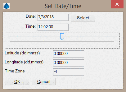
Date/Time: These values set the date and time for the lighting. The Select button will allow you to pick the date from a calendar. The horizontal slider below the time will allow you to set the time of day.
Latitude/Longitude: These values set the location of the viewpoint
Time Zone: This value adjusts for the various time zones. Values should be integers representing GMT adjustments. For example, the Eastern Standard Time (EST) in the USA will use a value of -5.
| Control | Action |
|---|---|

|
This control represents the position of the sun in plan view. If the yellow square is in the center of the blue circle, the sun is in a zenith. If the yellow square is near the edge of the circle, the sun is near the horizon. To move the yellow square, simply drag it to a new location, or click on the new location. The slider bars on the sides control the intensity and brightness of the display. |
| Switches to Pick
Mode. |
|
| Switch to Dynamic Zoom mode. Click and drag to zoom in and out. | |
| Switches to Rotation mode. When the cursor is placed near the outer edge of the view, a "Z" cursor is presented that permits rotation around the Z-axis. When the cursor is placed further into the interior of the view, an "X,Y" cursor is presented that permits the tilt angle of the view to be adjusted. | |
| Switches to Pan mode. Click and drag to pan. | |
| Starts (or "runs") the animation in the main window. While running, this button becomes the Stop button. | |
| Stops the animation. When stopped, this button becomes the Run button. | |
| Opens the help document you are currently reading. |
|
| Exits the command. |
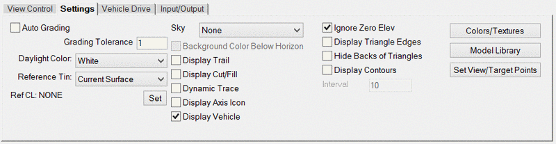
Auto Grading: This option automatically sets the Grading
Tolerance based on the elevation difference with the reference
TIN.
Grading Tolerance: When the cut/fill is less than this
amount, the surface will be colored by the Daylight
Color.
Daylight Color: The surface color for areas with
cut/fill less than the Grading Tolerance.
Reference TIN: When using a Reference TIN from the first
dialog, this option controls the direction of the cut to
fill.
Ref CL: When a
reference
centerline has been selected, the current view position is
reported beneath the main viewer window indicating the
station/offset relative to the centerline.
Sky: This option controls the background image for the 3D viewer. By default, no background image will be displayed. When a background image is displayed, you can toggle the Background Color Below Horizon checkbox to hide the bottom half of the background image.
Display Trail: Displays the traveled route on the surface as a line.
Display Cut/Fill: This displays the amount of cut or fill at the location of
the vehicle. This option is only available when a Reference TIN is used in the first setup
dialog.
Dynamic Trace: When enabled, a position marker of the current view point is also displayed in the CAD/DWG window.
Display Axis Icon: Shows an x/y/z
axis icon in the scene to help visualize the view
angles.
Display Vehicle: This option toggles the visibility of
the Vehicle int eh 3D view.
Ignore Zero
Elevation: Ignores zero elevation
entities in the scene.
Hide Backs of Triangles: This
option toggles the display of the backs of 3D Faces. When enabled,
even the edges of the triangles will be hidden.
Display Contours: Shows contours for
the surface using the specified Interval.
Colors/Textures: This button opens
the below dialog, which controls the colors and textures applied to
the surface.
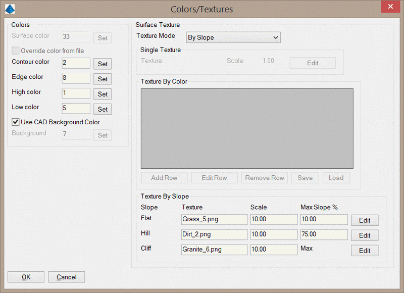
Surface Color: This setting will determine the color of surface entities when the shading mode is set to either flat or smooth. The color functions are only available when the Surface Source is defined by a File. If the Surface Source is defined by screen entities, color is determined by the properties of the screen entities.
Override color from file: When enabled, this option will override any color assignments and display the entire surface as a single color.
Contour/Edge color: These colors control the coloring for contours and triangle edges. Note that this does not affect the coloring of contour polylines that are loaded into the viewer, but only contours that are generated within the viewer.
High/Low Color: When using the "Elevation" mode of shading, these values set the color gradient of surface entities that are in the higher elevation ranges of the surface.
Use CAD Background Color: When enabled, the background color of the 3D viewer will match the CAD background color. If this option is disabled, you can set a different background color.
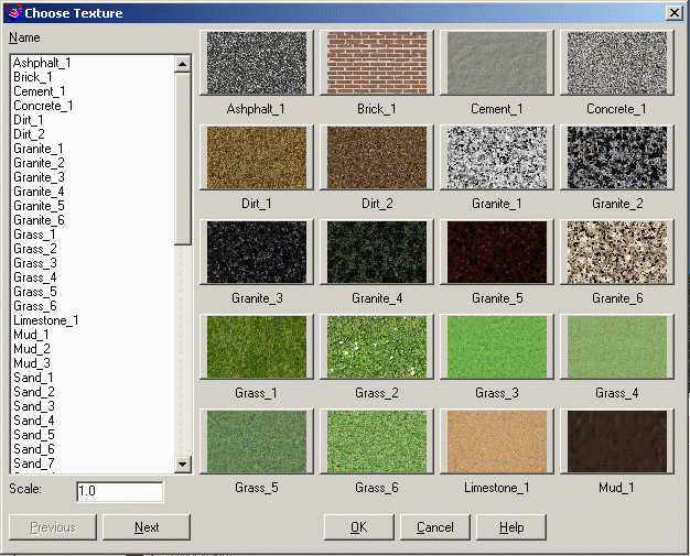
Surface Texture: This function controls the texture for the surface. There are five Texture Modes.
None: No textures will be used.
Single Texture: Sets one texture for the entire surface. Clicking the Edit button will display the below dialog, allowing you to select a texture and a scale for the image.
By Color: Sets a texture for each different color in the surface. The TIN file can have different colors for different areas by using the Road Network output TIN options to color by grade or by using Triangulation File Utilities. When this option is used, you will be able to add colors to the Texture by Color table.
By Color, Single as Default: This is the same as the By Color option except the Single Texture is used for any TIN colors not set in the lookup list.
By Slope: This option sets the texture of the surface according to the slope of the surface. The cutoffs for the three slope groups are set with the Max Slope % value for that field. The textures for each slope group may be set by clicking the Edit button.
Model Library: This button opens the 3D Model Library.
Set View/Target Points: This button opens the below dialog, which lets you set the
view position and target position by specifying the coordinates of
each.
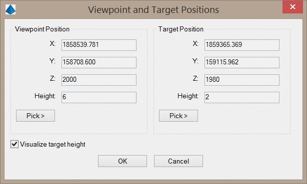
The positions can be entered in the edit boxes or you can use the respective Pick > button to pick a point in the drawing. The program will pick up the elevation of the surface for picked points and then the height above the position can be entered. For example, to check sight distance the view position could be a point on a road at the driver's eye height and the target position could be the object to check.
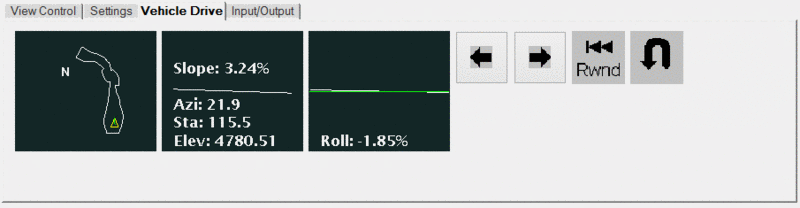
The window on the left shows the overall plan view and the location of the vehicle of the surface. The middle window displays the current station (when a polyline is used for direction control), elevation, slope (in relation to the direction of travel) and azimuth. The right window indicates the amount of roll or cross slope (in relation to the direction of travel) at your current position.
| Control | Action |
|---|---|

|
When using "Free Flight", this icon turns the direction of travel to the left. |

|
When using "Free Flight", this icon turns the direction of travel to the right. |

|
When using a 3D polyline for the travel direction, this button returns you back to the original starting position. The simulation must be in the Stopped mode for this to be active. |

|
When using a 3D polyline for the travel direction, this button will reverse the direction of travel at the current position. The simulation must be in the Stopped mode for this to be active. |
| Control | Action |
|---|---|

|
Adds a 3D Model to the viewer. |

|
Loads an MDL solid file. |

|
Loads a 3DX file. |

|
Sets the 3D Viewer viewpoint to match the current
CAD viewpoint. |

|
Reloads the data in the 3D Viewer. |

|
Save a screenshot of the 3D Viewer. |

|
Records a movie of the 3D Viewer. The video will
be saved to a .avi format. You will also be able to select from a
variety of compression methods. After clicking OK, the recording
will begin. You may click the icon again to stop the
recording. |

|
Sets the CAD viewpoint to match the current
viewpoint of the 3D Viewer window. |

|
Exports the 3D Viewer to a PDF report with project information. The default project information is set under Carlson Configure > General Settings. The dialog that appears for this command is shown below. |

|
Exports the 3D Viewer to a 3D PDF. This function is further described in the to the 3D Viewer to 3D PDF help article. Note that you must have access to the CADNET module in order to use this command. |

|
Save the entities in the 3D Viewer to a 3DX file. |
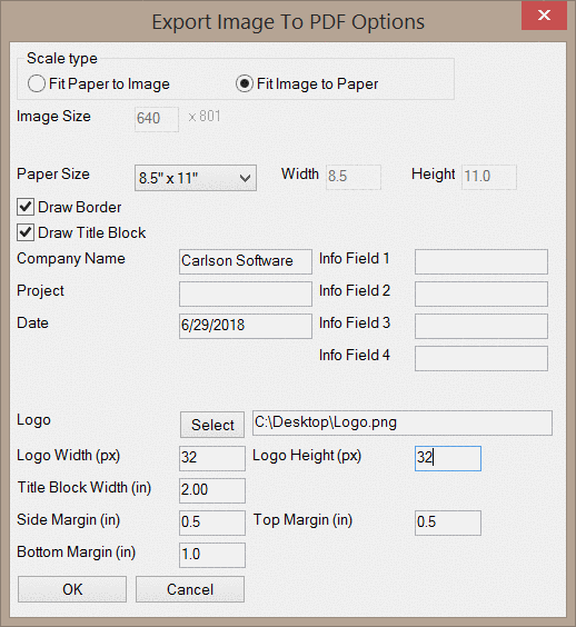
Scale Type: This option controls how the image and the paper will be scaled to match one another. When the Fit Paper to Image option is selected, you will be able to manually set the Image Size.
Paper Size: This option sets the size of the PDF.
Draw Border: This option toggles the addition of a border around the PDF.
Draw Title Block: This option toggles the addition of a title block in the PDF. Information such as the Company Name, Project, Date, and Logo will be included in the title block. The logo may be selected by clicking the Select button and the dimensions may be specified in pixel dimensions.
Top/Side/Bottom Margin: These values set the margins around the PDF in inches.
When a location is "picked" through a double-click while in pick mode, the following dialog box displays with additional controls about how the location should be processed:
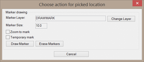
Marker Layer: Indicate a desired layer name or use the Change Layer button to select an existing layer for the position of an eventual marker.
Marker Size: Indicate the desired radius of a circle that will serve as the marker location.
Zoom to Mark: When enabled, the DWG will be zoomed to the location of the marker so it can be quickly found in the drawing.
Temporary Mark: When enabled, the marker will only be displayed in the drawing while the display remains static. As soon as a display update is summoned (via REDRAW, REGEN, ZOOM or PAN), the marker will no longer display on the screen. Disabling this toggle commits a CIRCLE entity into the drawing.
Draw Marker: Draws a marker into the drawing at the coordinates of the picked location and with the display characteristics defined by the Temporary Mark toggle.
Erase Markers: Erases any markers previously placed with the Draw Marker command.
Pulldown Menu Location(s): Civil > Surface > 3D
Views, Construction > Takeoff
Keyboard Command: flyby,(tk_flyby, tk_flyby2)
Prerequisite: A Carlson surface model (screen entities or
file) and optionally a 3D polyline