This command creates a cross section file (.SCT) from 3D
polylines. The 3D polylines should be drawn perpendicular to the
centerline. A section alignment file (.MXS) from the Input-Edit
Section Alignment command is needed to define the centerline and
the stations of the cross sections.
The elevations for the cross section points come from the 3D
polyline vertice elevations. The offsets for the cross section
points are derived from the perpendicular distance between the
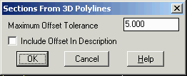
centerline and the polyline vertices. In order to be included in a
cross section, a polyline vertice must be within the Maximum
Offset Tolerance distance of the cross section line.
When using 3D Polylines drawn in cross section, they should be
drawn from left to right across the centerline. Use the Reverse
Polyline command if needed to change the 3D polyline
direction.
Choose MXS File to Process select file
Choose SCT file to Append/Write select
file
Sections From 3D Polylines dialog
Select polylines for sections.
Select objects: pick polylines
Pulldown Menu Location: Sections
Keyboard Command: sct3dp
Prerequisite: 3D Polylines and section alignment file
(.MXS)