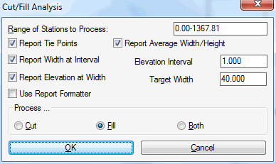
This command generates a report of the horizontal width of cut
and fill areas between two cross sections. The report generated can
take into account the cut, the fill or both. For example, the
Process option for Cut only will report only the grinding areas as
the cut end areas. The options for this command are set in the
dialog shown. The Report Width At
Interval option reports the width of each area is reported
at different elevations set by the Elevation Interval. For the
Report Elevation At Width
option, the elevation is calculated for where the area has the
Target Width. For the
Report Average Width/Height
option, the average width and height is calculated for each area.
The Report Tie Points
option reports the intersection points between the original ground
and design sections. The Use
Report Formatter option allows for customized reports and
output to Excel and databases.
Section File (Existing Ground) dialog choose existing
.SCT file
Section File (Final Ground) dialog choose the other
existing .SCT file
Cut/Fill Analysis dialog Make selections.
Cut/Fill Section Report is created.
Width Analysis Report:
Cut/Fill Section Report

Target Width: 20.00

Section 1: C:\data\simo2.sct

Section 2: C:\data\final.sct

Station: 0+10.000

Fill Area: 153.289

  Target Width at 108.07

  Area Above Target Width: 72.48

  Area Below Target Width: 80.81

  Average Width: 12.19

  Average Height: 2.95

  Elev: 110 Width: 25.97

  Elev: 105 Width: 10.65

  Elev: 100 Width: 2.86

  Elev: 95 Width: 0.00
Tie Points Report:
Section File 1: C:\sample\rehab1\exist-rd.sct
Section File 2: C:\sample\rehab1\grind.sct
Station Fill Area Tie Offset
Width Tie Offset Left Tie Offset Right Tie Elev
Left Tie Elev Right
732+58.510 12.941
24.000
-12.000
12.000
927.312
927.337
732+75.000 13.485
24.000
-12.000
12.000
927.381
927.288
733+00.000 13.554
24.000
-12.000
12.000
927.505
927.271