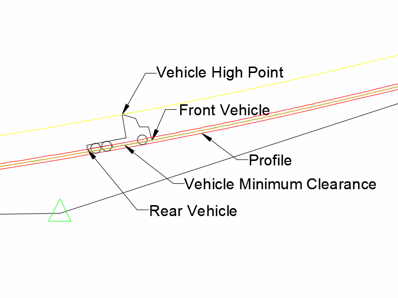
This command traces the vertical paths for vehicle dimensions along a profile. The profile is defined by a profile drawing which must be created before running this command. The center of the front axle, the center between the rear axle(s) and if selected the center of the trailer axle(s) follow the profile.
Select profile polyline: select a profile polyline from a Profile Drawing
After selecting the profile, the program will display the
Vehicle Path Tracking Profile dialog. The Vehicle Path Tracking
Profile dialog has three tabs; Vehicle, Trailer and Profile. Each
tab contains data for the corresponding component.
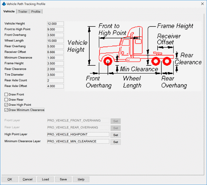
Vehicle Height: Height of vehicle at the highest point
from the ground.
Front to High Point: Distance between the front of vehicle
body to the highest point.
Front Overhang: Distance from front axis to front of vehicle
body.
Wheel Length: Distance from front axis to center of rear
axis.
Rear Overhang: Distance from rear axis to the back of the
vehicle body.
Receiver Offset: Distance from receiver to the back of the
vehicle body.
Minimum Clearance: Distance from ground to bottom of the
vehicle body.
Frame Height: Distance from ground to the top of the vehicle
frame.
Rear Clearance: Distance from ground to the bottom of the
vehicle frame.
Tire Diameter: Diameter of vehicle tires.
Rear Axle Count: Number of rear axles.
Rear Axle Offset: Distance between rear axles.
Draw Front: Draws the profile of the front low point of
vehicle body.
Draw Rear: Draws the profile of the rear low point of
vehicle body.
Draw High Point: Draws the profile of the high point of
vehicle body.
Draw Minimum Clearance: Draws the profile of the lowest
point of vehicle body between axles.
Front Layer: Layer to draw the profile of the front low
point of vehicle body on.
Rear Layer: Layer to draw the profile of the rear low point
of vehicle body on.
High Point Layer: Layer to draw the profile of the high
point of vehicle body on.
Minimum Clearance Layer: Layer to draw the profile of the
lowest point of vehicle body between axles on.
Set: Select the corresponding vehicle layer from
list.
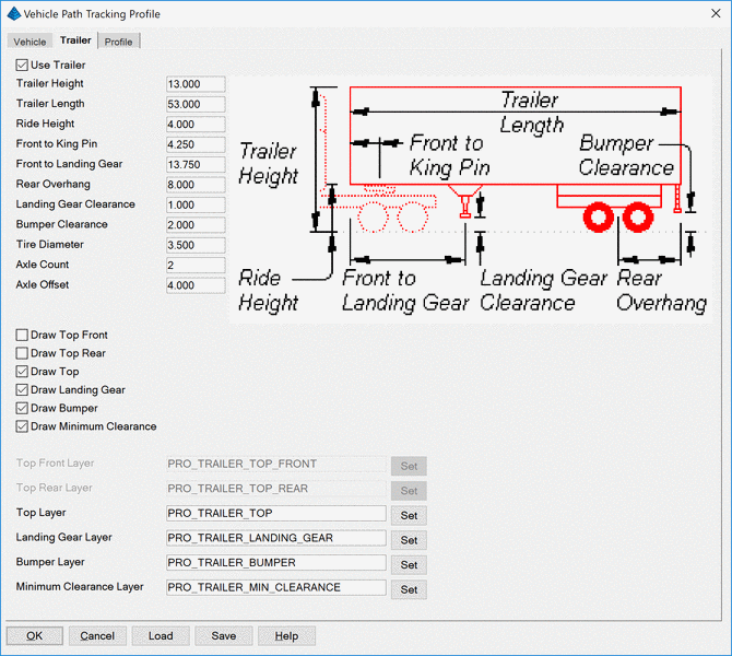
Use Trailer: Use this toggle to setup the trailer data
and choose profiles to draw.
Trailer Height: Height of trailer from the ground.
Trailer Length: Overall length of trailer.
Ride Height: Height of the bottom of the trailer from the
ground.
Front to King Pin: Distance from the front of the trailer to
the King Pin (Hitch Point).
Front to Landing Gear: Distance from the front of the
trailer to the landing gear.
Rear Overhang: Distance from rear axis to the back of the
trailer.
Landing Gear Clearance: Distance from ground to landing
gear.
Bumper Clearance: Distance from ground to the bottom of the
trailer bumper.
Tire Diameter: Diameter of trailer tires.
Axle Count: Number of trailer axles.
Axle Offset: Distance between trailer axles.
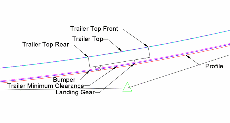
Draw Top Front: Draws the profile of the front high point of
the trailer.
Draw Top Rear: Draws the profile of the rear high point of
the trailer.
Draw Top: Draws the profile of the highest point of the
trailer between the front and rear.
Draw Landing Gear: Draws the profile of the trailer landing
gear.
Draw Bumper: Draws the profile of the trailer bumper.
Draw Minimum Clearance: Draws the profile of the lowest
point between the landing gear and the axle axis.
Top Front Layer: Layer to draw the profile of the top front
point of the trailer on.
Top Rear Layer: Layer to draw the profile of the top rear
point of the trailer on.
Top Layer: Layer to draw the profile of the top of trailer
between front and rear on.
Landing Gear Layer: Layer to draw the profile of the trailer
landing gear on.
Bumper Layer: Layer to draw the profile of the trailer
bumper on.
Minimum Clearance Layer: Layer to draw the profile of the
lowest point of the trailer between the landing gear and the axle
axis on.
Set: Select the corresponding trailer layer from list.
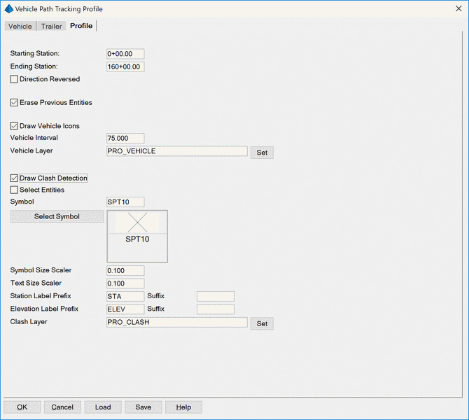
Starting Station: Starting station for vehicle and if
selected trailer profiles to be calculated.
Ending Station: Ending station for vehicle and if selected
trailer profiles to be calculated.
Direction Reversed: Draws the profiles from ending toward
starting stations.
Erase Previous Profile Entities: Removes previously drawn
profiles for selected profile.
Draw Vehicle Icons: Draws the vehicle and if selected
trailer icons.
Vehicle Interval: Interval distance between icons.
Vehicle Layer: Layer to draw the icons on.
Set: Select the icon layer from list.
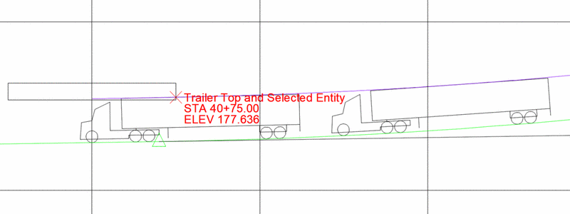
Draw Clash Detection: This option will detect locations
where the profile paths conflict with the selected Profile.
Select Entities: This option allows for additional CAD
objects to be selected and checked for conflicts with profile
paths.
Symbol: Symbol to place at the detected clash locations.
Select Symbol: Select symbol from the symbol library.
Symbol Size Scaler: Sets the size for the symbols at the
detected clash locations.
Text Size Scaler: Set the size of the labels for the
detected clash locations.
Station Label Prefix / Suffix: Prefix and Suffix for all
station labels placed at detected clash locations.
Elevation Label Prefix / Suffix: Prefix and Suffix for all
elevation labels placed at detected clash locations.
Clash Layer: Layer to draw the detected clash icons and
labels.
Set: Select the clash layer from list.
The Save and Load buttons save and recall the
vehicle dimensions to a .VTV file.