This command uses a 3D polyline to define Template Point Profile
and Template Point Centerline files which can then be used in
Process Road Design and Road Network to have a template grade
follow that 3D polyline. For example, the 3D polyline could define
the bottom of a ditch and this routine will create the road design
files needed to adjust the road template to follow the 3D polyline
for the ditch.
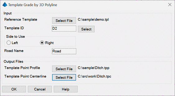
After selecting the 3D polyline, there is a dialog with the
input and output settings. The Template ID identifies the template
element to match to the 3D polyline. The Side To Use tells whether
the 3D polyline is for the left or right side of the centerline.
The Road Name is used for naming the centerline (CL) and profile
(PRO) files which are automatically named and placed in the same
folder as the Output Files. The Output Files define the names of
the Template Point Profile and Centerline files to create.
Pulldown Menu Location: Roads
Keyboard Command: prep_tpl_3dp
Prerequisite: 3D polyline