This command creates Carlson points along a horizontal alignment
polyline using a profile file to compute the point elevations. The
created points are stored in a coordinate (.CRD) file and can also
be drawn on screen in the layer specified by the user. Station
text, profile name, and special points (vertical and horizontal
PC's and PT's) can be stored in the point description depending on
user settings.
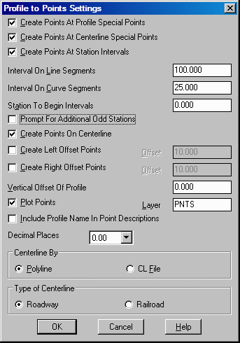
Create points at Profile special points: Includes
vertical PC and PT points.
Create points at Centerline special points: Includes
horizontal PC and PT points.
Create points at Station Intervals: Allows you to specify
intervals for point creation.
Interval On Line Segments: Specify station interval for line
segments.
Interval On Curve Segments: Specify station interval for
curve segments.
Station to Begin Intervals: Specify station to start
intervals.
Prompt For Additional Odd Stations: Any station can be
entered to create additional points with elevations derived from
the profile.
Create Points on Centerline: When checked, points will be
created on the centerline.
Create Left Offset Points: When checked, left offset points
will be created. Specify the offset in the edit box.
Create Right Offset Points: When checked, right offset
points will be created. Specify the offset in the edit box.
Vertical Offset of Profile: Specify the vertical offset.
Enter zero for no vertical offset.
Plot Points: When checked, points will be plotted in the
drawing, otherwise points are only added to the current coordinate
(.CRD) file.
Include profile name in point descriptions: When checked,
the profile name will be used as the prefix on the point
description. For example, if the profile name is DESIGN.PRO, then
the point description might be DESIGN 0+63.37.
Decimal Places: Specify the display precision for points
that are plotted in the drawing. This setting does not affect the
coordinates stored in the CRD file.
Centerline by: Click either Polyline or CL File.
Type of Centerline: Click either Roadway or Railroad.
OK: Specify files.
Select Coordinate File to Process
If the current coordinate is set, it is used automatically without
this prompt.
Select profile centerline polyline: pick a
polyline
Starting station of centerline <0.0>: press
Enter
Station by another reference centerline [Yes/<No>]?
N for no. This option will
prompt for a second centerline to use for stationing. With this
option, the first centerline is used for locating the points and
the second reference centerline is used for locating the profile
stations. So the first centerline represents where the points are
created (ie. the edge of pavement) and the second centerline
represents the profile location (ie. the road CL).
Choose Profile to Process dialog Specify a profile name.
Starting point number <1>: press Enter This
defaults to the point number after the highest one currently in the
CRD file.
Station for additional point (ENTER to end): press
Enter This option will create a point at the specified station.
Prompt occurs only if option is specified in dialog.
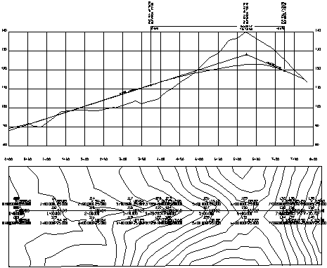
|
| Points created along profile centerline using elevations from the above road profile |
Keyboard Command: pro2pts
Prerequisite: A .PRO file and a centerline polyline