Edit-Assign Polyline Elevations
This command allows very precise control of 3D Polylines,
specifically in the ability to edit vertex elevations, as well as
add, delete, or move vertices. If these polylines are used in
the creation of surfaces as breaklines, any editing you do may
update the surface automatically. You can also control the location
of Polyline vertices as defined by the station and offset of the
vertices relative to a Centerline. Polyline vertices are
designated as either control or free vertices. The elevation
of control vertices are set and held, the elevations of free
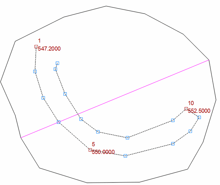
vertices are interpolated. In the drawing, control vertices
are shown by default with red boxes, free vertices with blue boxes,
but you may configure these using the Grip Color in the
Settings.
 Edit-Assign Polyline Elevations Dock Dialog:
When you run the Edit Assign Polyline Elevations routine, you are
first prompted to select a Polyline to edit. After selecting
a Polyline to edit, the following dock dialog appears on the left
side of your screen. This dialog is "modeless" meaning that CAD
commands and controls are still active while this dialog is
active.
Tabs:
The four tabs in the panel provide access to control of Polyline
vertex Elevation, Position, Offset and
Distance.
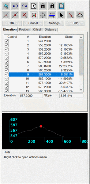
- Elevation: This
tab displays the vertices of the Polyline, each with a check box to
set whether it is a control vertex or a free vertex (Control), its
assigned number (#), its elevation (Elevation), and the slope from
the previous vertex to that vertex (Slope). Selecting a vertex
highlights its grip in the drawing. Once selected, you can
enter an "elevation" or "slope" edits for that vertex. If multiple
vertices are selected with varying elevation or slopes then
"[multiple]" will be displayed in the "Elevation" and or "Slope"
edits. When multiple vertices are selected, entering values in the
"Elevation" or "Slope" edits will set all selected vertices based
on the entered elevation or slope values.
- Position: The
Position tab displays the Easting and Northing coordinates of each
vertex. When one vertex is selected Northing and Easting can be
entered in the "Northing" and "Easting" edits. When Multiple
vertices are selected average Northing and average Easting are
displayed in the "Average Northing" and "Average Easting" edits.
When multiple vertices are selected entering values int eh "Average
Northing" and or the "Average Easting" edits will set all selected
vertices Northing and or Easting values to based on the entered
values.
- Offset: The
Offset tab requires the selection of a Centerline to
reference. Once a Centerline is designated, the Station and
Offset of each vertex relative to the Centerline is displayed and
can be edited.
- Distance: The Distance tab shows the horizontal distance
for each Polyline segment. You can change a distance by
highlighting the segment on the list and editing the value in the
"Horz Dist" edit. If multiple vertices are selected "[multiple]"
will be displayed in the "Horz Dist" edit. The user cannot set
multiple segment's horizontal distances at once.
Toolbar Commands:
The toolbar provides access to several commands, some of which are
tab specific.
 Revert All: Reverts currently selected
Polyline vertex positions and control information to vertex
positions and control information when Polyline was initially
selected. (Note: Selecting a new Polyline resets initial reversion
location)
Revert All: Reverts currently selected
Polyline vertex positions and control information to vertex
positions and control information when Polyline was initially
selected. (Note: Selecting a new Polyline resets initial reversion
location)
 Undo: Undoes the
most recent command line action. (Equivalent to ctrl+z)
Undo: Undoes the
most recent command line action. (Equivalent to ctrl+z)
 Redo: Redoes the
most recent command line action. (Equivalent to ctrl+y)
Redo: Redoes the
most recent command line action. (Equivalent to ctrl+y)
 Select Polyline: Select Polyline to edit.
(Note: if no Polyline is selected a Polyline can be selected using
CAD selection)
Select Polyline: Select Polyline to edit.
(Note: if no Polyline is selected a Polyline can be selected using
CAD selection)
 Control Selected: Set selected vertices
controlled, elevation will not be interpolated for control points.
(This toolbar command is only available when elevation tab is
active)
Control Selected: Set selected vertices
controlled, elevation will not be interpolated for control points.
(This toolbar command is only available when elevation tab is
active)
 Free Selected: Set selected vertices free>, elevation
will be interpolated for free points. (This toolbar command is only
available when elevation tab is active)
Free Selected: Set selected vertices free>, elevation
will be interpolated for free points. (This toolbar command is only
available when elevation tab is active)
 Output Report: Brings up Report Formatter
dialog. Output reports can contain Easting, Northing, and or
Elevation information for each vertex as well as whether or not
each vertex is controlled or free.
Output Report: Brings up Report Formatter
dialog. Output reports can contain Easting, Northing, and or
Elevation information for each vertex as well as whether or not
each vertex is controlled or free.
 Create Vertex: Creates a vertex at the station
nearest the mouse click position. Control/free state depends on the
"Create Vertex Mode" setting (see Settings dialog).
Create Vertex: Creates a vertex at the station
nearest the mouse click position. Control/free state depends on the
"Create Vertex Mode" setting (see Settings dialog).
 Create Vertex At Crossing: Prompts user to
select crossing Polyline(s). If Polyline(s) selection is(are)
applicable, crossing vertex point(s) are added at the elevation of
the selected Polyline(s) at crossing. All created vertices are
added as control points.
Create Vertex At Crossing: Prompts user to
select crossing Polyline(s). If Polyline(s) selection is(are)
applicable, crossing vertex point(s) are added at the elevation of
the selected Polyline(s) at crossing. All created vertices are
added as control points.
 Delete Vertices: Deletes currently selected
vertices.
Delete Vertices: Deletes currently selected
vertices.
 Reduce Vertices: Prompts user to select an
offset cutoff. Removes those vertices from the active Polyline that
will not change the position of the Polyline at that vertex by more
than offset cutoff. Will not removed controlled vertices.
Reduce Vertices: Prompts user to select an
offset cutoff. Removes those vertices from the active Polyline that
will not change the position of the Polyline at that vertex by more
than offset cutoff. Will not removed controlled vertices.
 Move Selected: Move currently selected
vertices based on drag offset. (Equivalent of click and drag)
Move Selected: Move currently selected
vertices based on drag offset. (Equivalent of click and drag)
 Reverse Polyline: Reverses indices of
vertices. This will be reflected by reversing the vertices in the
currently active list view.
Reverse Polyline: Reverses indices of
vertices. This will be reflected by reversing the vertices in the
currently active list view.
 Pick Elevation/Position From
Screen: Elevation- prompts user to pick an entity from screen.
Will set elevation based on entity's elevation information. Vertex
set controlled. Position-prompts user to pick position from screen
sets Northing and Easting based on selected position. (This toolbar
command is only available when elevation tab or position tab is
active).
Pick Elevation/Position From
Screen: Elevation- prompts user to pick an entity from screen.
Will set elevation based on entity's elevation information. Vertex
set controlled. Position-prompts user to pick position from screen
sets Northing and Easting based on selected position. (This toolbar
command is only available when elevation tab or position tab is
active).
 Pick Elevation From Surface: Prompts user to
select a surface model (tin;flt). Then prompts user to pick a
direction point to run the slope from highlighted vertex. Elevation
of highlighted point is determined from surface and slope is then
applied along the line to the next control point. (This toolbar
command is only available when elevation tab is active and one or
more vertices is selected).
Pick Elevation From Surface: Prompts user to
select a surface model (tin;flt). Then prompts user to pick a
direction point to run the slope from highlighted vertex. Elevation
of highlighted point is determined from surface and slope is then
applied along the line to the next control point. (This toolbar
command is only available when elevation tab is active and one or
more vertices is selected).
 Pick Elevation With Slope: Prompts user to
pick a point or elevation text. Then prompts user to pick slope. An
elevation is then calculated based on the run to the point selected
at the slope the user input. Elevated vertices will be set
controlled. (This toolbarcommand is only available when elevation
tab is active).
Pick Elevation With Slope: Prompts user to
pick a point or elevation text. Then prompts user to pick slope. An
elevation is then calculated based on the run to the point selected
at the slope the user input. Elevated vertices will be set
controlled. (This toolbarcommand is only available when elevation
tab is active).
 Offset Selected Elevation: Prompts user to
input an offset amount. Adds(subtracts) offset amount from
currently selected vertices. Offset vertices will be set
controlled. (This toolbar command is only available when elevation
tab is active)
Offset Selected Elevation: Prompts user to
input an offset amount. Adds(subtracts) offset amount from
currently selected vertices. Offset vertices will be set
controlled. (This toolbar command is only available when elevation
tab is active)
 Select Centerline: Prompts user to select a
Centerline or Polyline to apply Centerline information from screen.
(This toolbar command is only available when Offset tab is active)
Select Centerline: Prompts user to select a
Centerline or Polyline to apply Centerline information from screen.
(This toolbar command is only available when Offset tab is active)
OK:
The "OK" button closes the Edit-Assign Polyline Elevations dialog,
and saves the vertex position and control information of the
currently selected Polyline.
Cancel:
The "Cancel" button closes the Edit-Assign Polyline Elevations
dialog, and reverts the currently selected Polyline's vertex
position and control information to the vertex position and control
information when the Polyline was first selected.
Settings:
The "Settings" button provides control over various options
pertaining to the use of the Edit-Assign Polyline Elevations
routine.
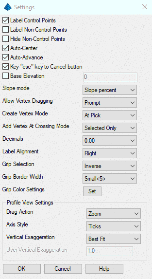
- Label Control Points: Toggle on to display control
vertices' numbers and elevations.
- Label Non-Control Points: Toggle on to display free
vertices' numbers and elevations.
- Hide Non-Control Points: Toggle on to remove all free
vertices' grips.
- Auto-Center: Toggle on to automatically center view such
that all currently selected grips when they are selected.
- Auto-Advance: Toggle on to automatically advance the
currently selected grip to the next available vertex (by vertex
number).
- Key "esc" key to Cancel button: Toggle on to key "esc"
to the Edit-Assign Polyline Elevations' dialog "Cancel" button.
That is pressing the "esc" key will cancel and exit the Edit-Assign
Polyline Elevations routine.
- Base Elevation: When toggled on the leading significant
digits of the Base Elevation value will be added as a prefix to any
elevation value entered. Base Elevation values must be whole
numbers greater than or equal to zero. Typical use: (Base:
6000)+(User: 100)=(Elevation: 6100 displayed as 100).
-
- Conflicts: Some user entered elevation values are
ambiguous in terms of how to combine the Base Elevation, and the
user entered elevation. These conflicts are dealt with as
follows:
-
- Significant Digit Conflicts: In the case where a user
entered value, and the Base Elevation value both contain
significant digits in the same column(s), then the user entered
value supersedes the Base Elevation value in that(those) column.
Ex: (Base: 6500)+(User: 100)=(Elevation: 6100 displayed as
100).
- Negative Value Conflicts: Negative values are processed
as values below the Base Elevation. However, adding a negative
value can result in elevations that result in "Significant Digit
Conflicts" with the Base Elevation. In this case the logic of the
"Significant Digit Conflicts" applies. Ex: (Base: 6000)+(User:
-100)=(Elevation: 5900 displayed as 5900).
- Slope Mode: Determines how slope at a vertex is
displayed and interpreted.
-
- Slope Ratio: Slope as a ratio of line length to line
elevation [run/rise]
- Slope Percent: Slope as a percent
[rise/run*100]
- Slope Degree: Slope as degree offset from 0?
from -90? to 90?
[atan(rise/run)*180/PI]
- Allow Vertex Dragging: Determines how dragging selected
vertices functions.
-
- Never: Never allow dragging.
- Prompt: On completion of vertex dragging user is
prompted on whether or not to accept the results of the dragging
operation.
- Always: Always allow dragging.
- Create Vertex Mode: Determines how elevation is
calculated for vertices inserted using the Create Vertex toolbar
command, double click on line, or right-click Create Vertex
command.
-
- On Line: Creates a vertex at the station nearest the
pick point. Elevation is interpolated based on the equation
[elv=(InsertDistance2D/TotalDisatance2D)*(TotalElevationChange)].
If no control points exist, then the elevation is set to the
elevation of all other free vertices on the Polyline. Inserted
vertex is a free point.
- At Pick: Creates a vertex at pick point. Vertex is
inserted in the Polyline after the vertex preceding the nearest
station to the pick point. If the pick point is the result of a
snap, the elevation of the new vertex is taken from the elevation
of the snapped entity, and the created vertex is added as a control
point. Otherwise, the created vertex is added as a free point.
- Add Vertex Crossing Mode: When running the function to
add vertices at crossings with other linework, this option chooses
whether to add intersection vertices on the crossing linework in
addition to the current polyline.
- Decimals: Determines how many decimal places are
displayed in Edit-Assign Polyline Elevations dialog. User can
choose between 0 and 6 decimal places for display.
- Label Alignment: Determines where vertex index, and
vertex elevation for all labeled vertices is drawn.
-
- Right: Draw label to the "right" of vertex grip. Takes into
account screen rotation.
- Top: Draw label "above" vertex grip. Takes into account screen
rotation.
- Grip Selection:
-
- Standard: left-click to drag vertex, shift+left-click to
select single grip vertex.
- Inverse: shift+left-click to drag vertex, left-click to
select single grip vertex. (legacy control)
- Grip Border Width: Allows user to set the relative size
of the gripbox for all vertices based on the internal ACAD/ICAD
GRIPSIZE variable. (Note: the values associated with each Grip
Border Width choice represent the value that the internal ACAD/ICAD
variable GRIPSIZE is set to for each Grip Border Width selection.
If the current GRIPSIZE ACAD/ICAD variable is not one associated
with any of the Grip Border Width choices ["Small," "Medium,"
"Large," "XLarge"] the Grip Border Width will be set to current
ACAD/ICAD GRIPSIZE.)
- Grip Color Settings: Set the grip colors for easier
editing of the vertices:
-
- Hover Vertex
- Control Vertex
- Free Vertex
- Profile View Settings:
-
- Drag Action: Choose between doing Zoom or Pan for click-n-drag
in the profile view.
- Axis Style: Set the profile grid display.
- Vertical Exaggeration: Control the display for the profile
vertical scale.
Help:
Display Carlson documentation for Edit-Assign Polyline
Elevations.
Right-click
Dialog:
There is a right-click menu available when the Edit-Assign Polyline
Elevations routine is running which gives access to a variety of
functions and settings. "Select All" and "Invert Selection" are the
only commands unique to the right-click dialog. "Select All"
selects all currently visible vertices. "Invert Selection" inverts
all currently visible vertices. "Undo," "Redo," "Create Vertex,"
"Reverse Polyline," "Pick New Polyline," "Delete Selected," "Move
Selected," "Control Selected," "Free Selected," "Offset Selected,"
"Pick Elevation," "Pick Elevation From Surface," "Pick Elevation
With Slope," and "Pick Position" are equivalent to the Toolbar
Command with the same name. "Label Control Points," "Label
Non-Control Points," "Hide Non-Control Points," "Auto-Advance," and
"Auto-Center" are equivalent to their settings dialog toggles with
the same name.

Pulldown Menu Location: 3D Data
Keyboard Command: EDIT_PLINE_Z
Prerequisite: 3D Polylines with vertices