


Control points are the global positions of the target points, and are a sub-item of the Instrument Data folder. There can be only one set of control points for a project. There are two ways to manipulate Control Points: the Right-Click menu or the Control Point Editor.
Note: Several commands are available in both the Right-Click menu and in the Control Points Editor. A command in the Right-Click menu operate on all control points. The Control Points editor commands operate on only the selected Control Points. If no control points are selected the users is asked if they wish to perform the operation on all control points.
| Edit | Launches the Control Point Editor |
| Delete All | Deletes all Control Points. The user is prompted via a dialog box to confirm the deletion. |
| Import | Launches the ASCII file import dialog box. |
| Export | Launches the ASCII file export dialog box. |
| Transform | Launches the Transform dialog box to allow the user to define a transformation sequence to apply to the control points. |
| View | Launches the Scene creation dialog box to create a scene for viewing the control points. |
| Draw | Draws the Control Points in CAD. The user is prompted via a dialog box for the layer to draw the Control Points on. |
To open the Control Point Editor, right-mouse click on Control Points under Instrument Data in the Current Project tree and then select Edit.
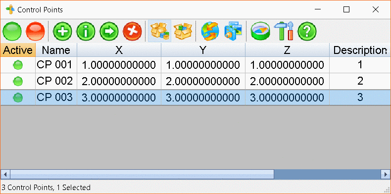
Along the top is a toolbar with several icons:
|
|
Activate Control Point toggles the selected control point(s) to be active in the current project. |
|
|
Deactivate Control Point toggles the selected control point(s) to be inactive in the current project. |
|
|
New Control Point brings up a dialog that allows users to specify the properties of a new control point to add. |
|
|
Edit Control Points brings up the point edit dialog which allows users to change properties of the currently selected Control Point. |
|
|
Copy Control Points allows users to copy the currently selected Control points to another point set (such as from the control points to the target points of a scan). |
|
|
Delete Control Points deletes the currently selected control points. |
| Import Control Points brings up the ASCII file import dialog. | |
|
|
Export Control Points brings up the ASCII file export dialog. |
|
|
Transform Control Points allows users to define a transformation sequence to apply to the control points. |
|
|
View Control Points brings up the scene creation dialog to create a scene for viewing the current control point set. |
|
|
Coordinate System allows users to choose the coordinate system the positions values are in (Global or any of the current scan positions) |
|
|
Settings allow users to configure what properties of the control points are visible in the spreadsheet control. |
|
|
Help brings up help documentation. |
Name will specify a unique name to be used for the Control Point in the Project.
X, Y and Z are the coordinates of the Control Point.
Description allows users to add information that describes the new Control Point.
Target Points allows the user to specify Target Points from any Scan to be referenced to the new Control Point.
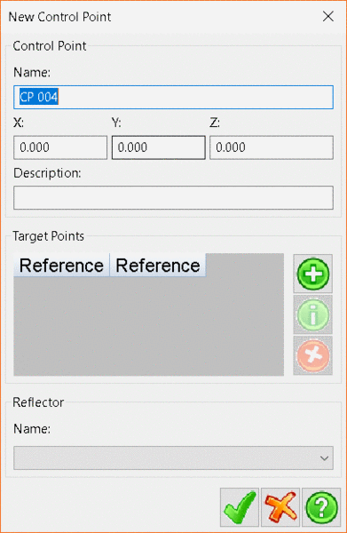
Adds a new reference Target Point. Allows the user to edit the selected reference Target Point Deletes the selected reference Target Point
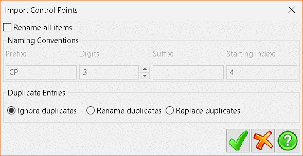
Clicking the Import button opens the Import Control
Points window. Navigate to the correct file and click
Open.
Currently supported file import types are TXT, CSV,
CRD and CRDB.
Once the file has been opened, the Import Control Points
dialog will display.
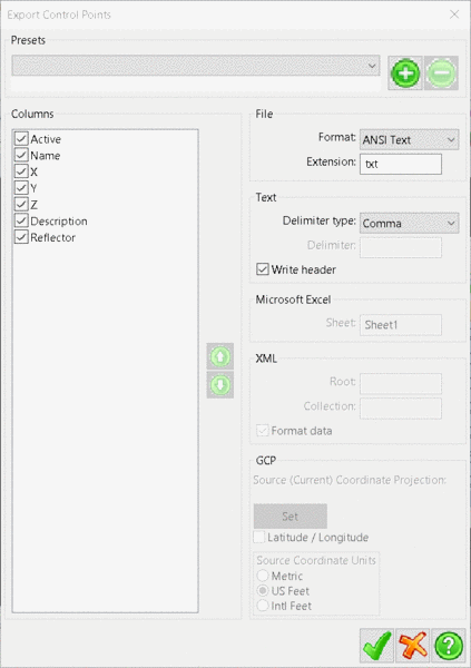
Clicking the Export
Points button will open
the Export Control
Points window, which allows users to export
the data to several different file formats.
In the Columns panel,
click on the check boxes to include or exclude the data elements.
To change the order of the data elements in the file, click on the
element and then click the up or down arrows to adjust its
position.
The File panel
determines which file format to export to and also allows you to
specify an extension other than the default for a given file
format.
The Text panel
contains options when exporting to the different text file
types, ANSI
Text or Unicode
Text. The Delimiter
Type determines the divider between data
elements in the file. The Write
header option specifies whether to write
a header line to the file detailing the data ordering of the
file.
Microsoft Excel allows the user to define
the name of the Excel worksheet that the points will be exported
to. Note: only available when exporting
as Format: Microsoft Excel.
XML allows users to define
the Root and Collection values
and choose to Format
data. Note: only available when
exporting as Format:XML.
GCP - when exporting as GCP, click on
the Set button to choose
the Coordinate Projection. Users can choose to select a Pre-Defined
projection, add a projection from a file or create a User-Defined
projection on the fly.
Click OK to select and
return to the previous window. Users can select to export the
coordinates in Latitude/Longitude format and also to select the
appropriate
units; Metric, US
Feet or International
Feet.
Users can select a preset export format by selecting it from
the Presets drop-down
menu. To define a new preset, include or exclude the desired data
elements in the Columns panel,
organise the elements into the desired order and then click
the Green
Plus button
next to the Presets drop-down.
The new preset will be added to the drop-down menu for future
use.
To delete a preset, select it from
the Presets drop-down
menu and then click the Green
Dash button
next to the Presets drop-down
menu.
The Transform button opens the Transform Coordinate Points window where users can define a selection of transformation parameters to apply to the selected Coordinate Points.
Initially, the dialog will have no transformations specified. To
add a transformation, press the Green
Plus button. which will open
the New
Tranformation window.
Use the Type drop-down
menu to select one of the four Transformation types:
Translate allows the user to define a translation of the current data set by specifying offsets in X, Y and Z.
Rotations allow the user to rotate the current selection set by specifying rotations around the X Y and Z axis.
Scaling allows the user to scale the current selection by a set Factor in the X, Y and Z axis.
Advanced allows the user to specify a transformation matrix to be applied to the data.
After clicking the check button, users will be taken back to
the Transform
Control Points window.
From here users can add more transformations, modify the currently
selected one by pressing
the Green
i button,
delete them by pressing the Red
X button,
or change their order of application to the data using
the Green
arrow buttons.
Press the Green
Tick button
to apply the transformations.
Note: Transformations are applied in
top-to-bottom order.
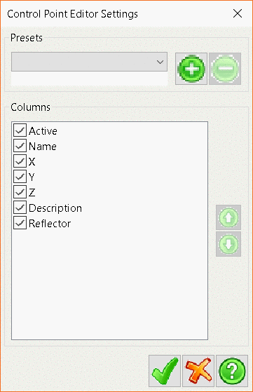
The Settings button will bring up the Control Point Editor Settings window, which allows the user to configure which data elements of the current point set are visible, as well as the order that they are displayed in.
To turn off a data element so it will not be displayed, click in
the check box next to that element in
the Columns panel.
To change the order that data elements are displayed, select the
element to move and then click the green up and down arrows to
adjust the elements position.
Users can select a preset export format by selecting it from
the Presets drop-down
menu. To define a new preset, include or exclude the desired data
elements in
the Columns panel,
organise the elements into the desired order and then click
the Green Plus button
next to
the Presets drop-down.
The new preset will be added to the drop-down menu for future
use.
To delete a preset, select it from
the Presets drop-down
menu and then click the Green
Dash button next to
the Presets drop-down
menu.
Tab Location(s): Project Tab
Panel and Button: Current Project and Control Points
Prerequisite: None