


The Polyline Editor window can be opened by right-mouse
clicking on a polyline in the Current Project tree and
selecting Edit or by double clicking on a polyline in the
Current Project tree. The Polyline Editor can also be
accessed when creating a new polyline from the Action tab.
Under the Active Polyline panel, highlight a polyline
and click Edit.
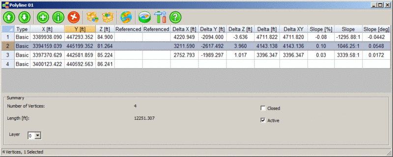
Along the top is a toolbar with several icons. The icons and their corresponding functions are as follows:
|
|
Move Vertices up will move the selected vertex or vertices up one position each time it is clicked. |
|
|
Move Vertices Down will move the selected vertex or vertices down one position each time it is clicked. |
|
|
Add Vertex brings up a dialog that allows you to specify the properties of a new vertex to add. |
|
|
Edit Vertex brings up the edit vertex dialog which allows you to change properties of the currently selected vertex. |
|
|
Delete Vertices deletes the currently selected vertex or vertices. |
| Import Vertices brings up the Carlson file selection dialog. | |
|
|
Export Vertices brings up the ASCII file export dialog. |
|
|
Transform allows you to define a transformation sequence to apply to the vertices. |
|
|
Coordinate System allows you to choose the coordinate system the positions values are in (Global or any current scan positions). |
|
|
Settings allow you to configure what properties of the vertices are visible in the spreadsheet control. |
|
|
Help brings up help documentation. |
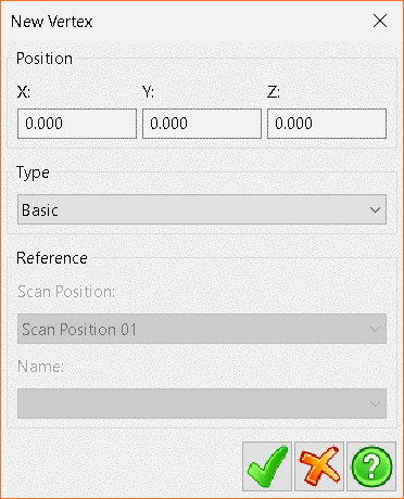
Clicking the Add Vertices button will bring up the New Vertex dialog.
X, Y, and Z are the x, y, and z coordinates
values for the new vertex to be added.
Type can be either Basic, Target Point
Reference or Coordinate Point Reference.
The Reference Panel is activated when the vertex type is set
to Target or Coordinate Point Reference.
When using Target Point Reference, select the desired scan
position from the drop-down menu and then select the correct target
point from those available in the Name drop-down menu.
When using Coordinate Point Reference, select the desired
coordinate point from thse available in the Name drop-down
menu.
Clicking the Import button will bring up the Import
Polyline file selection window. The currently supported file
types for polyline import are TXT, PLN and
CL.
Navigate to the correct polyline file and click
Open.
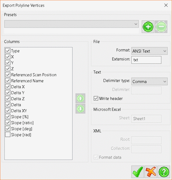
Clicking the Export button will open the Export
Polyline Vertices dialog, which allows users to export the
polyline to several different file formats.
In the Columns panel,
click on the check boxes to include or exclude the data elements.
To change the order of the data elements in the file, click on the
element and then click the up or down arrows to adjust its
position
The File panel
determines which file format to export to and also allows you to
specify an extension other than the default for a given file
format.
The Text panel
contains options when exporting to the different text file
types, ANSI
Text or Unicode
Text.
The Delimiter
Type determines
the divider between data elements in the file.
The Write
header option
specifies whether to write a header line to the file detailing the
data ordering of the file.
Microsoft Excel allows
the user to define the name of the Excel worksheet that the points
will be exported to. Note:
only available when exporting as Format:
Microsoft Excel.
XML allows
users to define the Root and Collection values
and choose to Format
data.
Users can select a preset export format by selecting it from
the Presets drop-down
menu. To define a new preset, include or exclude the desired data
elements in the Columns panel,
organise the elements into the desired order and then click
the Green
Plus button
next to the Presets drop-down.
The new preset will be added to the drop-down menu for future
use.
To delete a preset, select it from
the Presets drop-down
menu and then click the Green
Dash button
next to the Presets drop-down
menu.
The Settings button will bring up the Polyline Editor Settings window, which allows the user to configure which data elements of the current vertex set are visible, as well as the order that they are displayed in.
To turn off a data element so it will not be displayed, click in
the check box next to that element in
the Columns panel.
To change the order that data elements are displaued, select the
element to move and then click the green up and down arrows to
adjust the elements position.
Users can select a preset export format by selecting it from
the Presets drop-down
menu. To define a new preset, include or exclude the desired data
elements in
the Columns panel,
organise the elements into the desired order and then click
the Green Plus button
next to
the Presets drop-down.
The new preset will be added to the drop-down menu for future
use.
To delete a preset, select it from
the Presets drop-down
menu and then click the Green
Dash button next to
the Presets drop-down
menu.
Tab Location(s): Project Tab and Action Tab
Access Command: Right-Click Points and select Edit (Project
Tab) Click Edit button (Action Tab
- Polyline Creation mode)
Prerequisite: Scene with a polyline