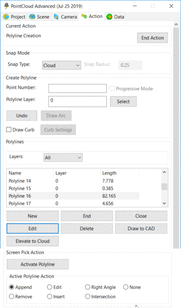
Create Polyline
Selecting the Polyline button from the Create
panel in the Action tab will open the Polyline
Creation dialog.
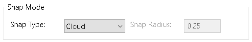
Snap Mode Panel
The Snap Mode Panel offers twelve different options for snapping
to points in the cloud in the open scene.
Cloud - No snap function is active.
The vertex of the polyline will be placed at the cloud point
nearest to the selected location.
Low - The polyline vertex is placed at the lowest
point (smallest z value) within the Snap Radius.
High - The polyline vertex is placed at the
highest point (largest z value) within the Snap Radius.
Low Edge - Snaps to the low edge of a feature. A
dynamic window in the upper left of the scene displays a cross
section of the area within the Snap Radius and displays the high
and low edge as red squares.
High Edge - Snaps to the high edge of
a feature. A dynamic window in the upper left of the scene displays
a cross section of the area within the Snap Radius and displays the
high and low edge as red squares.
Slope Bottom - Snaps to the bottom edge of a
slope that is less than 45 degrees. This is useful for finding low
edges on mountable curbs and other non-vertical features.
Slope Top - Snaps to the top edge of a slope that is less than
45 degrees. This is useful for finding upper edges on mountable
curbs and other non-vertical features.
Average Point - This snap averages Northing, Easting and
Elevation for all points within the Snap Radius and uses the
averaged values for the coordinate for the new polyline
vertex.
End Point - Snaps the new polyline vertex to the
endpoint of existing polylines.
Mid Point - Snaps the new polyline vertex to the
midpoint of existing polylines.
Node - Snaps the new polyline vertex to points
placed in the drawing using Carlson Point Cloud.
Nearest - Snaps the new polyline vertex to the
point on an existing polyline nearest to the cursor location.
High/Low Edges - Snaps to the high and low edges of a
vertical curb or wall simultaneously drawing two
poylines.
Create Polyline Panel
The Create Polyline Panel sets options for creating polylines
from the Point Cloud. Each option is discussed below.
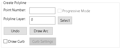
Point Number - Creating a Polyline by
Point Number allows the user to automatically draw polylines
between points that have been defined using the Create Point
command. Type the starting point number in the Point Number field
and press enter. Type the next point number and press enter. A
polyline will be drawn between the numbers entered. Continue
entering point numbers to draw more segments. The point numbers
must be defined in the Coordinate Points list found on the
Project tab.
Segment Mode - Note: Segment mode can only be used
when the Snap Type is set to High Edge or Low Edge. Segment Mode
creates a best fit polyline between the two selected points by
breaking the distance into smaller segments with length equal to
the snap radius. A point is found at each new segment location and
a best fit line created through the resulting points.
Polyline Layer - Users can specify the layer to
draw the new polyline on by typing a name in the Polyline layer
field. Users may also click the Select button and select any layer
currently in the scene or they may create a new layer to be used by
typing it at the bottom of the Select Polyline layer dialog
box.
Undo - Removes the last polyline segment drawn and
allows the user to continue the polyline creation from the previous
endpoint.
Draw Arc - Draws a three point arc in the current
polyline using the last point selected as the PC. The user is
prompted to specify second point on arc. A line will display for
the PC to the POC. After selecting the second point the user is
prompted to specify end point of arc. The arc is drawn and the line
from the PC to POC is gone.
Draw Curb - The draw curb toggle when selected
activates the Curb Settings Button
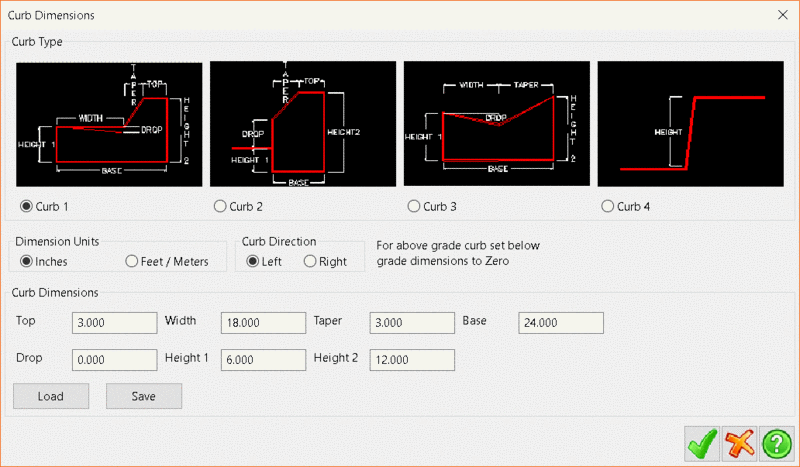
Curb Settings window
There are four curb types to choose from by clicking the radio
button below the desired type. The dimensions for each curb
can be specified using either feet or inches. The curb direction is
relative to the direction you select the curb points
in.
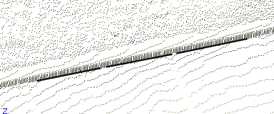
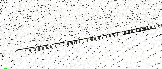
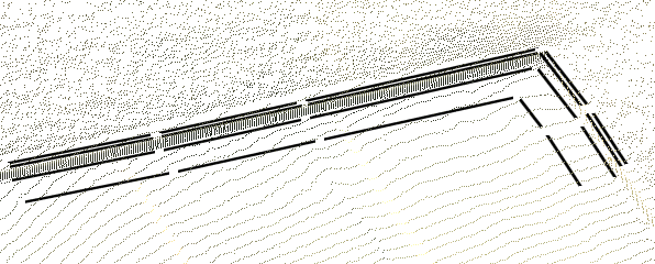
The polyline created from the picked points will be
named like any other polyline. The additional polylines created
from the draw curb routine will include the name of the main
polyline and a suffix number.
Below is an example of polylines created using Curb Type 1.
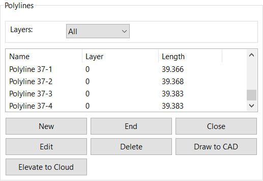
New - Starts a new polyline
End - Ends the polyline that is highlighted in the
list of Active Polylines
Close - Closes the current polyline to its
starting point
Edit - Opens the Edit Polyline dialog box. The
Edit Polyline dialog box can also be accessed by double clicking a
polyline from the
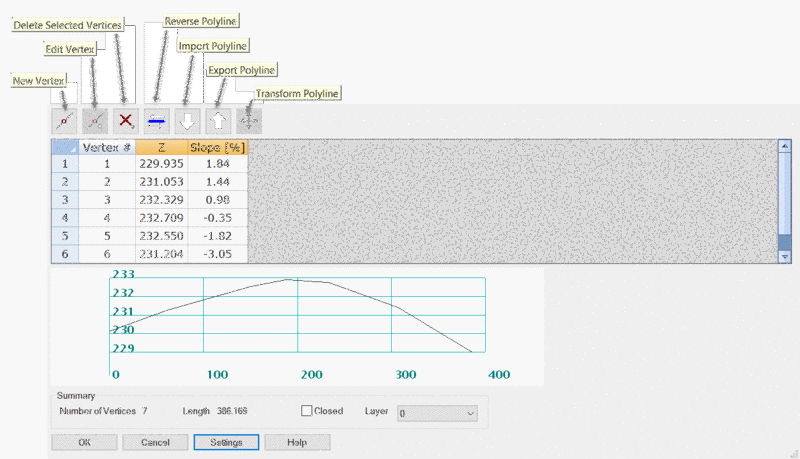
Options for editing are:
- New Vertex
- Edit Vertex
- Delete Selected Vertices
- Reverse Polyline
- Import Polyline
- Export Polyline
- Transform Polyline
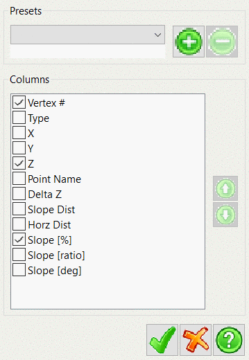
The Settings Menu controls the display
options for the Edit Polyline Dialog box
Delete - Deletes the selected polyline
Draw to CAD - Draws the active polylines into the
current CAD file.
Elevate to Cloud - elevates the selected polyline to the
cloud.
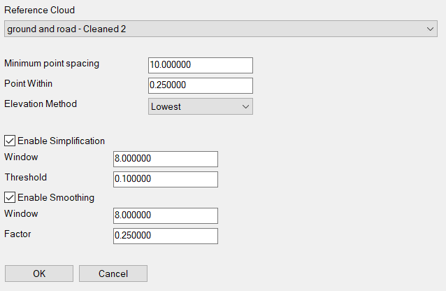
Reference Cloud - Specifies the cloud to use for elevating
the polyline.
Minimum point spacing - sets the spacing to add vertices along
the polyline as it intersects the point cloud
Point Within - specifies the radius of that the command will
consider for the snap selection
Elevation Method - sets the snap to one of four options for
the elevation
- Lowest
- Highest
- Average
- Median
Enable Simplification - Sets controls to simplify the
polyline as it is elevated to reduce the amount of vertices
Enable Smoothing - Sets controls to smooth the polyline as
it is elevated.
Screen Pick Action
The Screen Pick Action Panel provides options for editing
polylines in the active scene. Each option is discussed below.
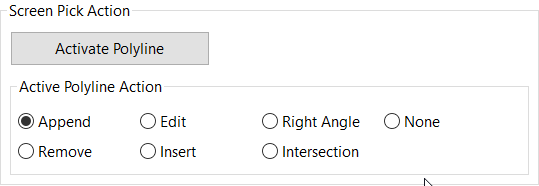
Activate Polyline - Allows the user to
select the polyline to activate for the editing process. The
Activate button can be used to make a polyline previously drawn
active again so you can add on to that polyline. The user is
prompted to select the polyline to activate. Multiple polylines can
be activated. Click the End Activate button before trying to work
with one of the activated polylines.
Append - appends (or continues) the currently selected
Polyline.
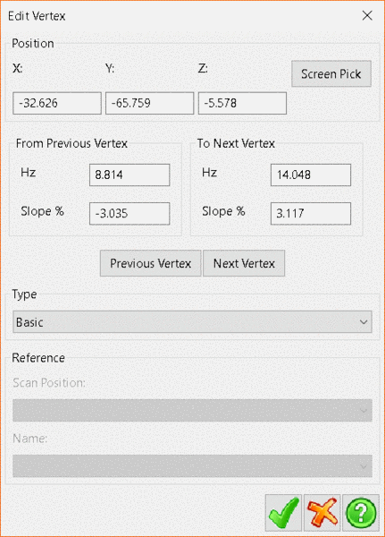
Edit - The user selects the polyline to be edited by
clicking on it in the current Scene. After selecting a polyline the
user is prompted to pick point on polyline to edit by clicking on
the point. The dialog box below is presented to the user.
The user can change the coordinates by typing in the X, Y or Z
fields or by clicking on a new position in the current Scene (click
the Screen Pick button). There are buttons to advance to the Next
vertex or return to the previous vertex along the polyline. The
user can also change the point type from Basic to Coordinate Point
reference.
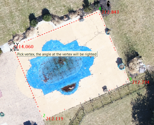
Right
Angle - Forces a vertex to be at a 90 degree angle from two
Polyline segments. The user selects the vertex and the command will
create a right angle at that point in the polyline
None - sets the Edit Mode to none to prevent unintended
edits being made.
Remove - Removes selected point from polyline
Insert - Inserts a new point into the polyline
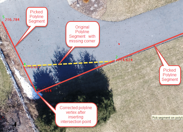
Intersection - creates a vertex at the point of intersection
of two polyline segments and modifies the polyline with the new
location.
Panel and Button: Create Polyline
Prerequisite: Open Point Cloud Scene